Home
Intel
Computer Hardware
EP80579
Page 46 (Form Factor of Intel EP80579 Development Board)
Intel EP80579 - Form Factor of Intel EP80579 Development Board
82 pages
Manual
Save Page as PDF
To Next Page
To Next Page
To Previous Page
To Previous Page
Loading...
Intel
®
EP8057
9 Integra
ted Proce
ssor with I
ntel
®
QuickAssist Technology—Technic
al Reference
Development Kit User’s Guide
October 2008
46
Order Number: 320067-002US
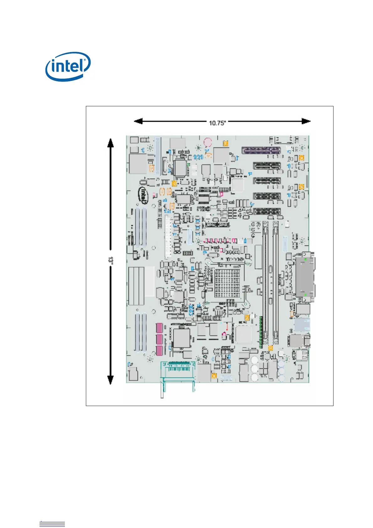
Figu
re 15.
Fo
rm Fact
or of
Inte
l
®
EP80579 Developm
ent Board
Downloaded from
Arrow.com.
Downloaded from
Arrow.com.
Downloaded from
Arrow.com.
Downloaded from
Arrow.com.
Downloaded from
Arrow.com.
Downloaded from
Arrow.com.
Downloaded from
Arrow.com.
Downloaded from
Arrow.com.
Downloaded from
Arrow.com.
Downloaded from
Arrow.com.
Downloaded from
Arrow.com.
Downloaded from
Arrow.com.
Downloaded from
Arrow.com.
Downloaded from
Arrow.com.
Downloaded from
Arrow.com.
Downloaded from
Arrow.com.
Downloaded from
Arrow.com.
Downloaded from
Arrow.com.
Downloaded from
Arrow.com.
Downloaded from
Arrow.com.
Downloaded from
Arrow.com.
Downloaded from
Arrow.com.
Downloaded from
Arrow.com.
Downloaded from
Arrow.com.
Downloaded from
Arrow.com.
Downloaded from
Arrow.com.
Downloaded from
Arrow.com.
Downloaded from
Arrow.com.
Downloaded from
Arrow.com.
Downloaded from
Arrow.com.
Downloaded from
Arrow.com.
Downloaded from
Arrow.com.
Downloaded from
Arrow.com.
Downloaded from
Arrow.com.
Downloaded from
Arrow.com.
Downloaded from
Arrow.com.
Downloaded from
Arrow.com.
Downloaded from
Arrow.com.
Downloaded from
Arrow.com.
Downloaded from
Arrow.com.
Downloaded from
Arrow.com.
Downloaded from
Arrow.com.
Downloaded from
Arrow.com.
Downloaded from
Arrow.com.
Downloaded from
Arrow.com.
Downloaded from
Arrow.com.
45
47
Table of Contents
Main Page
Default Chapter
3
Table of Contents
3
Introduction
8
Document Organization
8
Related Documents
9
Acronyms
9
Acronym Table
9
Product Specification
11
Overview
11
Product Description and Board Architecture
11
Block Diagram of the Intel EP80579 Development Board
12
Feature List
13
Package Components
13
System I/O
14
Intel ® EP80579 Development Board I/O
14
Super I/O (SIO)
14
PEX 8508 PCI Express* Switch
14
Marvell* 88E1141 Quad Ethernet Transceiver
15
System Memory
15
DDR2 Memory Configuration
15
Supported DIMM Slot Populations
16
Supported Operating Systems
16
Supported Pre-Boot Firmware Features
16
Pre-Boot Firmware Features
16
Intel ® EP80579 Development Board Overview
17
Intel ® EP80579 Development Kit Revision Identification and Color Scheme
17
Mezzanine Cards
18
Intel ® EP80579 Development Board
18
Power Supply
19
Ordering Information
19
Mezzanine Cards
19
System Overview
20
Power Distribution
20
Power Distribution Block Diagram
21
Platform Clocking
22
Clock Block Diagram
22
Platform Reset
23
Reset Diagram
23
Smbus
24
Smbus System Block Diagram
24
Technical Reference
25
Board Components Layout
25
Front View of the Board Components
25
Back View of the Board Components
26
Side View of the Board Connectors
27
Component and Connector Layout Description
27
IA-32 Core Frequency Selection
28
Smbus Address
29
Intel ® EP80579 IA-32 Core Frequency Selection
29
Smbus Connectivity
29
System Leds
30
Layout of Leds
30
Signal and Voltage LED Indicators
30
Fixed I/O Map and Interrupts
31
Jumper Block
31
Jumper Block Locations
32
Jumper Block Descriptions
32
SPI and FWH Boot Option Jumpers
34
Header Blocks
35
Header Locations
35
Header Block Descriptions
35
Connector/Header Pinout Information
36
ITP-XDP Connector Pinout
36
ITP-XDP Connector
36
ATX12V Power Connector Pinout
37
Main ATX Power Supply Connector
37
LEB Compactflash* Connector Pinout
38
HSS Mezzanine Connectors Pinout
38
HSS to Mezzanine Organization
38
HSS Interrupt GPIO Pin Names
38
Standard Mezzanine Connector Pinout
38
Expansion Mezzanine Connector
40
CAN Header Pinout
42
IEEE 1588-2008 Hardware-Assist Header Pinout
42
IEEE 1588-2008 Hardware-Assist Signal Header Pinout
42
Front Panel Header
43
Smbus Header
43
Front Panel Header Pinout
43
Smbus Header Pinout
43
SSP Header
44
SIO Tertiary (Third) UART Header
44
JTAG Access Headers
44
SSP Header Pinout
44
Tertiary UART Pinout
44
Intel ® EP80579, PEX8508 and 88E1141JTAG Header Pinout
44
GPIO Header
45
Mechanical Considerations
45
Form Factor
45
FPGA JTAG Header Pinout
45
GPIO Header Pinout
45
Form Factor of Intel ® EP80579 Development Board
46
Electrical Considerations
47
DC Loading
47
PCI Express Add-In Connector Considerations
47
DC Loading Characteristics Mode
47
Fan Connector Current Capability
48
Thermal Considerations
48
Pre-Boot Firmware
49
Introduction
49
Pre-Boot Firmware Boot Flow
49
Pre-Boot Firmware Features
49
Pre-Boot Firmware Setup Menu
49
Serial Console Redirection
50
Pre-Boot Firmware Setup Main Menu
50
Pre-Boot Firmware Setup Program Function Keys
50
Default Settings
51
PXE Boot Support
51
System Management BIOS (SMBIOS)
51
Legacy USB Support
51
Pre-Boot Firmware Recovery and Updates
51
Serial Console Redirection Default Settings
51
Updating Pre-Boot Firmware
52
Ami's Aptio* Flash Update Utility (AFUEFI)
52
Boot Options
53
Changing the Boot Device
53
Booting Without Attached Devices
54
Security Features
54
Clearing CMOS
55
CMOS Location
55
Platform Setup
56
Setting up the Platform
56
Safety
57
Intel ® EP80579 Development Kit Basic Setup
57
Connecting the SATA Cables
58
Connecting SATA Port 0
58
Installing Memory
59
Close-Up of Connection SATA Port 0
59
Memory Installation - 1 GB DDR-800 DIMM in DIMM 0 Socket
59
Connecting the Processor Heatsink and Fan
60
Proper Installation of Heatsink
60
Installing the PCI Express Video Card
61
Location of CPU FAN Connector
61
Graphics Adapter Installation - Pice Slot 0
61
Connecting the Keyboard and Mouse
62
Connecting the Serial Cable for Console Redirection
62
Connecting the PS/2 Keyboard and PS/2 Mouse
62
Connecting the CAN Interface Cables (Optional)
63
Connecting the DVD-ROM Drive and Gbe Ethernet Port
63
Connecting the Power Cables
63
Connecting the CAN Interface Cables
63
Connecting Ethernet Cable Port 0
63
Stand-Alone Target Platform
64
Connecting ATX Power Supply Cable
64
Powering up the System
65
Intel ® EP80579 Stand-Alone Target Platform
65
Connecting Mezzanine Cards (Optional)
66
Connecting the Mezzanine Cards (Optional)
67
Error Messages and Beep Codes
68
Pre-Boot Firmware Beep Codes
68
Pre-Boot Firmware Error Messages
68
Debugging the EFI
68
Beep Code Types
68
Socketed Intel ® EP80579 Integrated Processor with Intel ® Quickassist Technology
69
Tools and Preparation
69
EP80579 Processor Location
70
Advanced Interconnections 1088 POS PGA-To-BGA Socket
71
Advanced Interconnections 1088 BGA-To-PGA Interposer (Pin Side Facing Up)
72
Extraction Instructions - Intel ® EP80579 Development Board with Advanced Interconnects Interposer
73
Insertion Instructions - Intel ® EP80579 Development Board with Advanced Interconnects Interposer
78
Other manuals for Intel EP80579
Guide
347 pages
Related product manuals
Intel E7500
35 pages
Intel Embedded Intel486
334 pages
Intel Core i7 Extreme Edition
102 pages
NUC 13 Extreme Kit NUC13RNGi7
31 pages
NUC 13 Extreme Kit NUC13RNGi9
31 pages
EM64T - Celeron D 336 Boxed Ena
105 pages
E6700 - Core 2 Duo Dual-Core Processor
126 pages
E6600 - Core 2 Duo Dual-Core Processor
71 pages
QX9770 - Core 2 Extreme Quad-Core Processor
123 pages
E2180 - Pentium Dual-Core 2.00GHz 800MHz 1MB Socket 775 CPU
148 pages
E1400 - Celeron 2.0GHz 800MHz 512KB Socket 775 Dual-Core CPU
148 pages
E2160 - Cpu Pentium Dual-Core 1.80Ghz Fsb800Mhz 1M Lga775 Tray
55 pages