Intel
®
EP80579 Integrated Processor with Intel
®
QuickAssist Technology—Technical Reference
Development Kit User’s Guide October 2008
36 Order Number: 320067-002US
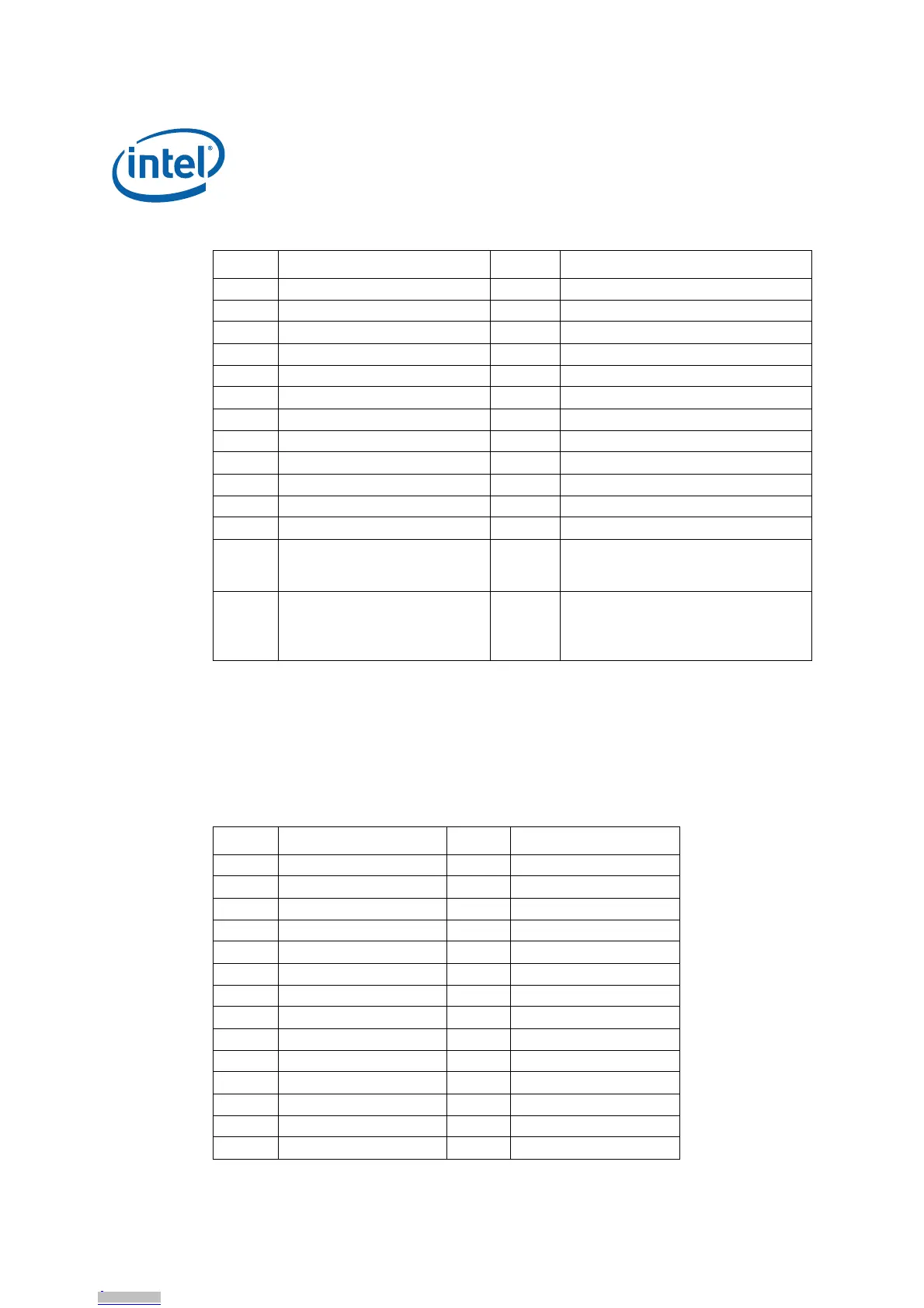
4.8 Connector/Header Pinout Information
4.8.1 ITP-XDP Connector Pinout
The Intel
®
EP80579 Development Board provides a 60-pin ITP-XDP connector for
system debugging purposes. For ITP-XDP pinout, refer to Table 15.
FSMBUS_B J4F3Table 24
GSMBUS_C J4F4Table 24
H VSBY_SMB J5E1 Table 24
ISIO1 SMBUS J1G2Table 24, connected to Board ID EEPROM
JSIO2 SMBUS J1G3Table 24, connected to PCIe slot
KSSP J4J1Table 25
L COM3 (Tertiary SIO UART) J2J1 Table 26
MIntel
®
EP80579 JTAG J5G2 Table 27
N 88E1141 JTAG J8E1 Table 27
O PEX 8058 JTAG J3E2 Table 27
P FPGA JTAG J9E5 Table 28
QGPIO header J7F1Table 29
RIntruder J3H4
Optional intruder switch header:
1: MICH_INTRUDER
2: GND
SCPU thermal diode J1H1
Access to processor thermal diode:
1: CPU_THERM_DC
2: CPU_THERM_DA
3: GND
Table 14. Header Block Descriptions (Sheet 2 of 2)
Location Header Name Ref Des Pinout Signal Description
Table 15. ITP-XDP Connector (Sheet 1 of 2)
Pin Name Pin Name
1GND 2GND
3PREQ_N 4NOA_CLK_0
5PRDY_N 6NOA_CLK_1
7GND 8GND
9 BPM_3 / NOA_0 10 NOA_8
11 BPM_2_N / NOA_1 12 NOA_9
13 GND 14 GND
15 BPM_1_N / NOA_2 16 NOA_10
17 BPM_0_N / NOA_3 18 NOA_11
19 GND 20 GND
21 NC 22 NC
23 NC 24 NC
25 GND 26 GND
27 NOA_4 28 NOA_12