Intergas Heating Ltd
19
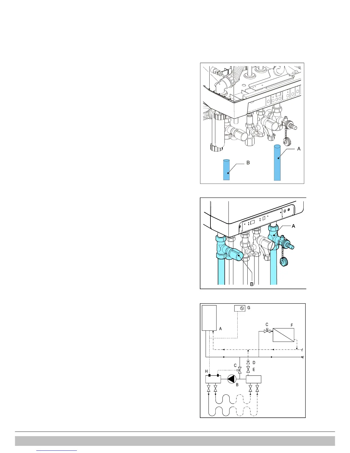
6. CONNECTIONS
6.1 Connect the CH system
1. Flush the CH system thoroughly.
2. Mount the flow and return pipes to the mounting bracket.
All pipes must be mounted tension-free in order to avoid ticking of the
pipes.
Existing connections must not be twisted in order to avoid leaks at the
connections with the external pipes.
The CH system should be provided with:-
• A filling/draining tap (A) in the return pipe immediately below the
appliance.
• A drain tap at the lowest point(s) of the installation.
• A 3 bar pressure relief valve (B) in the supply pipe at a maximum
distance of 500 mm from the appliance.
There must be no valve or constriction between the appliance and the
overflow valve.
• An expansion vessel in the return pipe.
• A check valve, if pipes run upwards at a short distance from the
appliance. This avoids the occurrence of thermosiphon effect during
DHW operation mode.
6.1.1 Expansion vessel
The appliance is fitted with a expansion vessel adequate for a system with a
water volume not exceeding 100 litres, typically 8 radiators. For larger volume
systems, an additional expansion vessel must be fitted. Contact Intergas for
advice in these cases.
6.1.2 Thermostatic radiator valves
If all radiators are equipped with thermostatic or regular radiator valves, a
bypass must be fitted in order to guarantee minimum water circulation. The
bypass must be at a distance of at least 6 m from the appliance in order to
prevent overheating of the appliance.
6.1.3 Underfloor heating
For a good operation of the domestic hot water supply, there must be no
undesired circulation through the appliance caused by a second pump of the
CH circuit.
Connect underfloor heating with an electric shut-off valve (two-way valve) to
prevent circulation through the appliance when there is no demand for central
heating.
A. Boiler
B. Pump
C. Thermostatic control valve
D. Spring-operated non-return valve
E. Electrical shut-off valve 230 V ~
F. Radiators
G. Room/clock thermostat
H. Maximum thermostat

 Loading...


