EasyManuals Logo

Intergas Rapid 25 Installation Manual

Intergas Rapid 25
60 pages
To Next Page IconTo Next Page
To Previous Page IconTo Previous Page
Page #22 background imageLoading...
Page #22 background image
Intergas Heating Ltd 22
6.3 Electrical connection
CAUTION
An earthed wall socket must be located no more than 1
metre from the appliance.
The wall socket must be easily accessible.
For installation in damp rooms a fixed connection is
obligatory.
When workin on the ectrical circuit always remove the
plug from the wall socket
If the mains lead has to be replaced, this should be carried
out by the manufacturer
A. Unscrew screw (A) to gain access to the burner manager (B).
B. Pull the burner manager unit forwards; the burner manager will tip
downwards to provide access.
C. Consult sections 6.3.1 and 11.2 for the making the connections.
D. After making the desired connections plug the appliance into an
earthed wall socket.
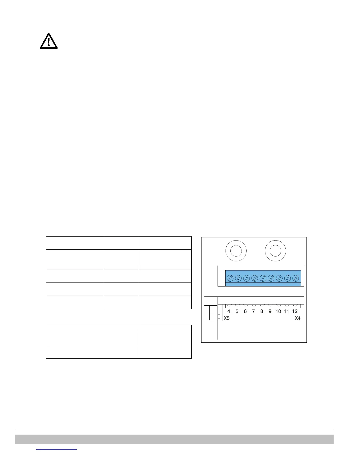
6.3.1 Electrical connections
Temperature control
Connector
X4
Notes
Room thermostat
6
7
Voltage free room
thermostat.
Remove link 6-7
Outside temperature
sensor
8
9
-
Frost protection
thermostat
6
7
Parallel to room
thermostat
Open Therm (OT)
11
12
Remove link 6
-
7
Temperature control
Connector X2
Notes
Room thermostat 230 V
or external control 230 V
1
3
Remove link 6
7
(connector X4)
Frost thermostat 230 V
1
3
Remove link 6
7
(connector X4)

Table of Contents

Other manuals for Intergas Rapid 25

Questions and Answers:

Question and Answer IconNeed help?

Do you have a question about the Intergas Rapid 25 and is the answer not in the manual?

Intergas Rapid 25 Specifications

General IconGeneral
Boiler TypeCombi
DHW Output25 kW
Efficiency Rating93%
Flow Rate10.2 l/min
MountingWall Mounted
ERP EfficiencyA
Max Gas Rate2.78 m³/h
Dimensions (H x W x D)590 x 450 x 240 mm

Related product manuals