Intergas Heating Ltd 28
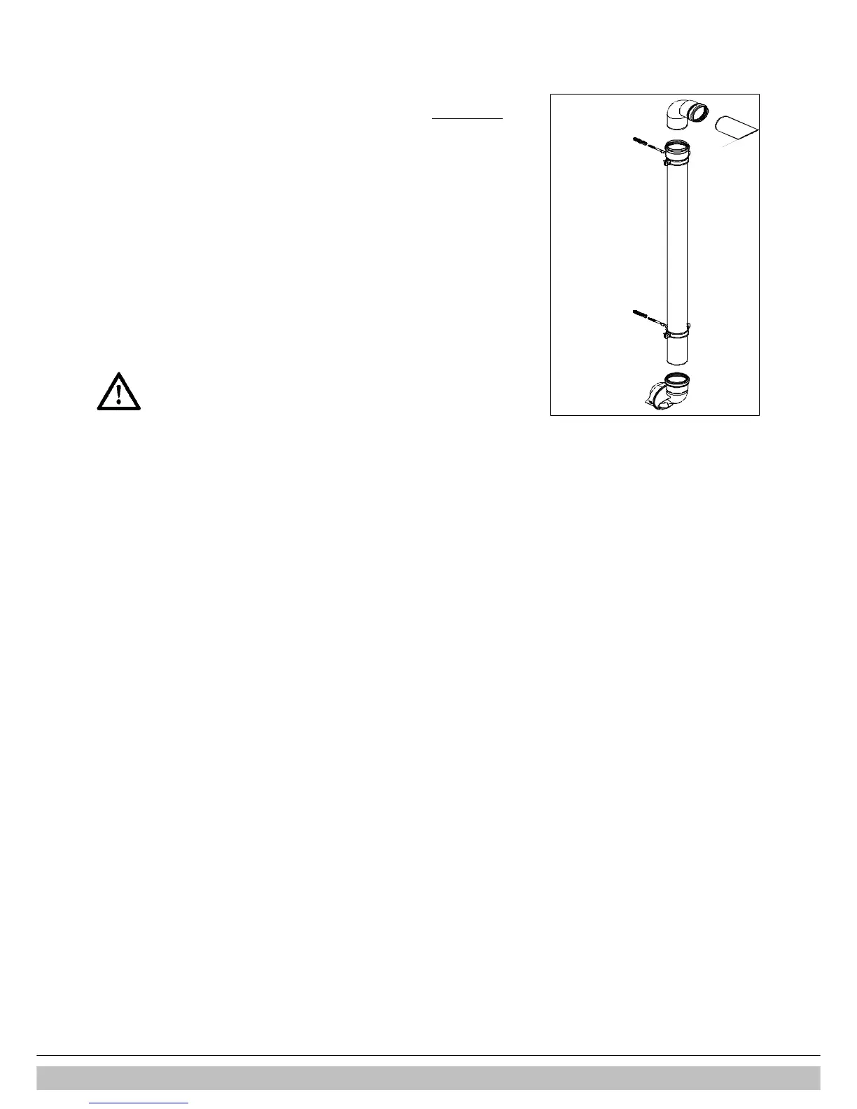
6.5.6 Plume management kit
The plume management kit comprises of a 710 mm horizontal section with elbow
to connect the 1m vertical condensing tube, which has a horizontal or vertical
terminal dependant on your requirements. The maximum length of horizontal flue
including the terminal but excluding the initial elbow from the boiler and 1 metre
vertical condensing tube is 7 metre.
Note
For each additional 90º elbow used the maximum flue length must be reduced by
1.5 metre, whilst the use of 2 x 45º bends warrants a reduction of 2 metre.
The horizontal part of the flue must be installed under a 3° fall towards the boiler (50
mm per metre) and must be supported with a minimum of 1 bracket at each meter
length. Best recommended position of the bracket is just before the joint.
6.5.7 Flues in voids
The flue system must be connected in accordance with the manufacturers instructions
BEFORE firing the boiler.
The term void includes ceiling voids, floor voids, purpose built enclosures ,service
risers, roof spaces or any other enclosure that will restrict access to inspect the flue.
To allow visual inspection, without reliance on devices such as endoscopes, cameras
and mirrors, inspection hatches must be provided along the entire length of the flue.
Hatches must be a minimum of 300mm x 300mm and positioned with the edge of the
inspection hatch to 1.5m of any joint and at changes of direction. Bends should be
viewable from both directions where the inspection hatch cannot be positioned at the
bend.
Where suitable access is not provided the appliance MUST NOT be commissioned and
must be disconnected from the gas supply.
Additionally the entire flue and all flue seals must be installed in accordance with the
requirements of BS5440:
1. Check condensate trap is filled with water and correctly connected to boiler.
2. All flue joints are correctly made, unstressed and adequately supported.
3. All parts of the flue can be visually inspected -ensure suitable access where flue is
positioned within voids-
• Sealing rings should only be moisturized with water before use. Do not use
soap or other detergents.
• When installing flues in voids make sure they are connected and
fixed correctly. If in an existing situation a visual inspection is not
possible the boiler must not be commissioned and remain
disconnected from the gas supply untill suitable access has been
realised.
• Make sure to follow the manufacturer’s instructions regarding
maximum length of the flue system, the appropriate flue material,
correct jointing methods and the maximum distance between flue
support.
• Ensure that all joints and seams are gastight and watertight.
• Ensure the flue system has a uniform gradient back to the boiler.

 Loading...


