Intergas Heating Ltd
41
8.9.2 Checking flue gas at minimum power
Before measuring the flue gasses at minimum output the measurement of the maximum
output must be completed. The measured O2 or CO2 value at maximum output is important
for determining the correct value for the measurement at minimum output. See § 8.9.1 for
measuring at maximum output
1. Activate the test program for maximum output by simultaneously pressing the buttons and
. A capital L appears in service display.
2. Wait until the reading of the analyser is stable (min. 3 minutes)
3. Note the measured value O
2
(L) orf CO
2
(L).
O
2
(L) = is the measured value of O
2
at minimum power
CO
2
(L) = is the measured value of CO
2
at minimum power
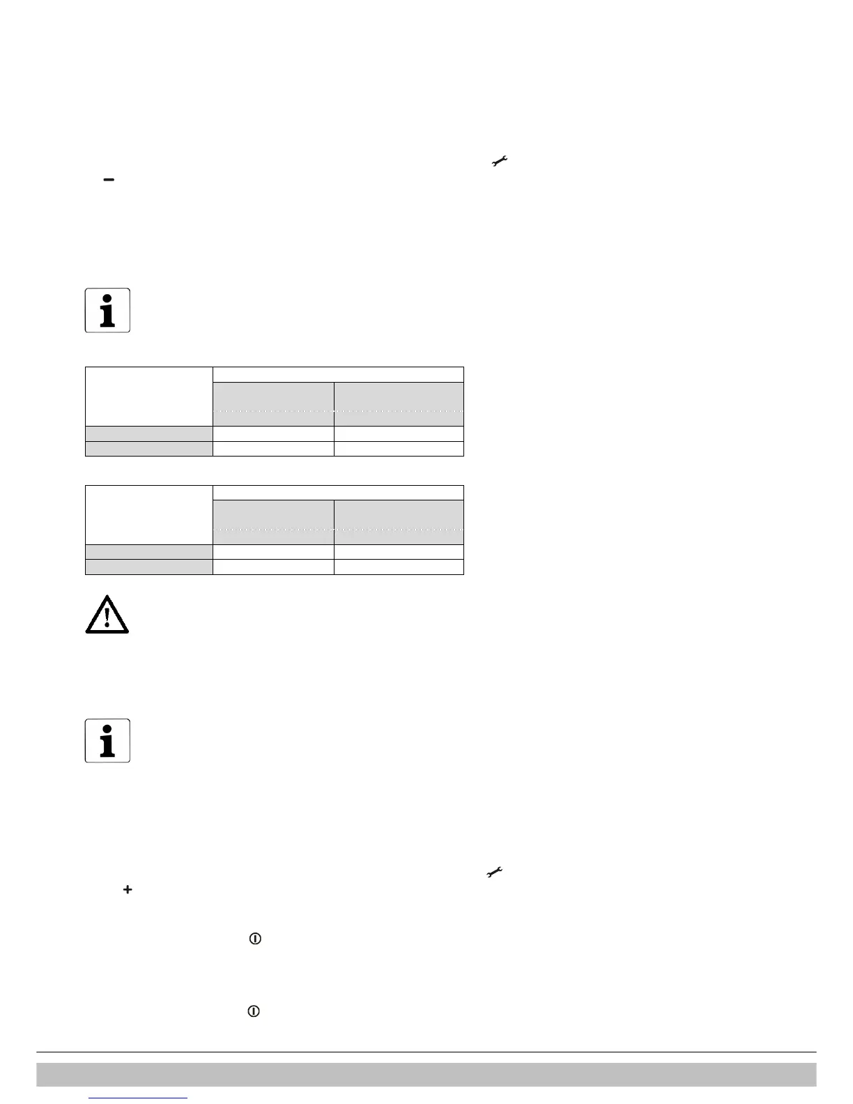
4. Check if the measured value is in accordance to the data in table 3a or 3b
The O2 lower limit is the value of O2(H) noted during the measurement at
maximum output . The CO2 upper limit is the value of CO2(H) noted during
the measurement at maximum output . (See § 8.9.1)
Table 3a: limits O
2
(L) at minimum output (open casing)
Gas category
Limits Natural gas
G20
Propane 3P
G31
O
2
[%] O
2
[%]
Maximum value 6.00 6.65
Minimum value O
2
(H) O
2
(H) + 0.5
Table 3b: limits CO
2
(L) at minimum output (open casing)
Limits
Gas category
Natural gas
G20
Propane 3P
G31
CO
2
[%] CO
2
[%]
Maximum value CO
2
(H) CO
2
(H) – 0.3
Minimum value 8.4 9.4
Important
• The gas-air ratio is set correctly when the measured value at
minimum output is within the upper and lower limit.
gas-air ratio is not advised.
• The gas-air ratio needs to be adjusted in accordance to § 8.9.3
when the measured value at minimum output is not within the
upper and lower limit.
For example (Natural gas G20)
During maximum output a O2(H) value of 4.0 % has been measured. In
that case the O2(L) value at minimum output must be in-between 4 %
(= value O2(H) and 6.05% as stated in the table. When during
minimum output a value out of this range is measured the gas-air ratio
must be adjusted..
5. Proceed, in case of a deviating value by adjusting the gas valve in accordance to § 8.9.3.
In case of a correct setting continue with point 6.
6. Fit the front panel to the appliance and tighten the 2 screws.
Check the values for CO at minimum output (= max. 160 ppm)
7. Activate the test program for maximum output by simultaneously pressing the button
and twice.
A capital H appears in service display.
Check the values for CO at maximum output (= max. 160 ppm)
Switch the appliance off with the button .
8. Remove the measuring probe of the flue gas analyser and replace the cap on the
sampling point.
9. Check the tightness of the sampling point
11. Switch the appliance off with the button and check that the appliance is functioning well.

 Loading...


