Intergas Heating Ltd
21
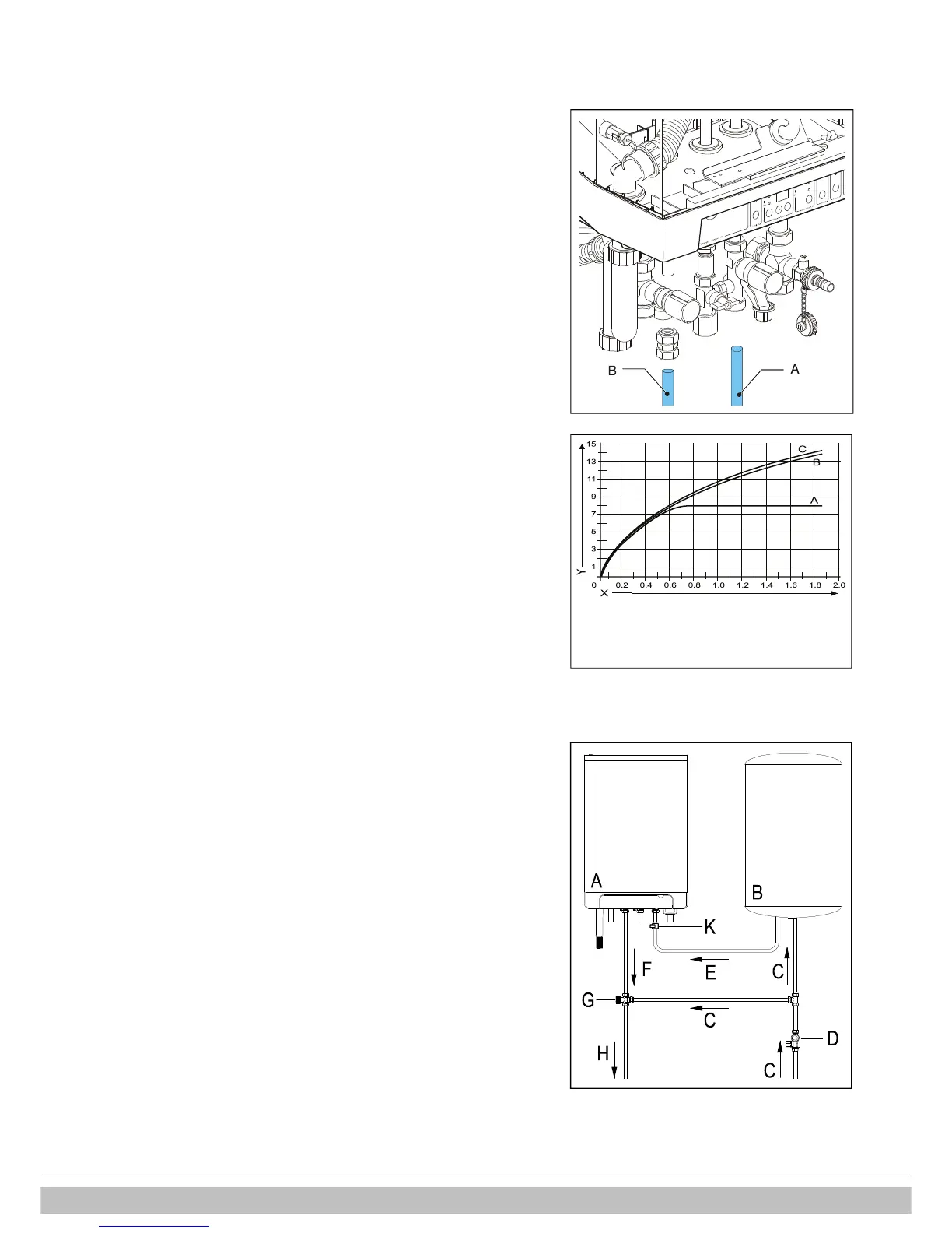
6.2 Domestic hot water system
A. Flush the installation thoroughly to clean (please refer to current Standard
Codes of Practice).
B. Fit the cold and hot water pipes into the shut off valve and the elbow.
A. Existing connections must not be twisted, in order to avoid leakages.
Make sure the compression fittings are tightened thoroughly to prevent
leakage.
Notes
• If the appliance is only used for the provision of hot water, the heating
function can be switched off by entering the service menu and change
parameter 1.
The CH installation does not then have to be connected or filled.
• If the appliance is taken out of operation during the winter and disconnected
from the mains supply, the DHW water must be drained in order to prevent
freezing. For this purpose the DHW connections below the appliance must be
removed.
Flow Resistance graph for appliance DHW circuit
A. Not applicable
B. Rapid 25
C. Rapid 32
X. kPa (Bar)
Y. Litres per minute
6.2.1 Appliance with solar water heater post-heating
The appliance carries the NZ label: suitable for “solar water heater post-heating”.
A special connection kit is applicable for this purpose.
Connection diagram for solar heater post -heating
A. Boiler
B. Storage tank Solar water heater
C. Cold water inlet
D. Inlet assembly
F. T max 85°C
G. Hot water outlet
H. Thermostatic mixing valve 40° - 90°C (set to aproxx. 55°C)
K. Mixed water outlet
Note
When combined with a solar power system a thermostatic mixing valve must
always be fitted after the appliance and set to approx. 55°C.

 Loading...


