Intergas Heating Ltd 44
9. FAULTS
9.1 Faultcodes
When the service display or the operating panel is flashing, the burner controller has detected a
fault. In case of several faults, the temperature display shows an additional code.
After the fault has been remedied, the burner controller can be restarted by pressing the reset
button on the operating panel.
The following faults are detected and displayed:-
Check the wires for breaks
Check the wires for breaks
Check the wires for breaks
•
Replace boiler sensor S1 and/or S2
•
Pump does not run
•
Too little circulation in system, radiators closed,
pump setting too low
No flame signal after 4 ignition
•
Incorrect ignition distance
•
Gas inlet pressure too low or disappears
•
Gas valve or ignition unit does not receive voltage
No flame signal after 4 restart
Condensate discharge blocked
•
Check setting of gas valve
•
Check earth
•
Replace ignition unit
•
Replace burner controller
•
Wiring between fan and casing
•
Check the wires for poor contact (tacho signal)
•
Replace fan
Replace the outside sensor
Always use original Intergas spare parts when replacing
components.
Failure to fit the sensors S1 and/or S2, or to fit them correctly
can result in serious damage.
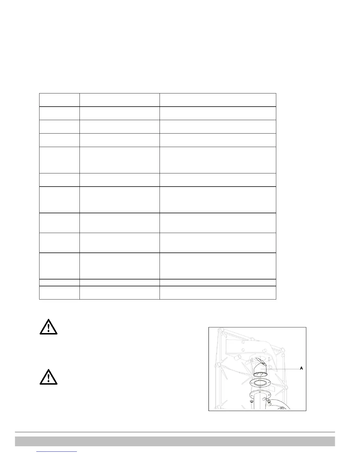
* The boiler is equipped with a non-return valve (A),
positioned above the fan. Ensure the non-return valve
is repositioned correctly when replacing the fan.

 Loading...


