Intergas Heating Ltd 40
8.9 Checking the gas air ratio control
8.9.1 Checking flue gas at maximum power.
1. Switch the appliance off with the button .
[-] will appear in service display.
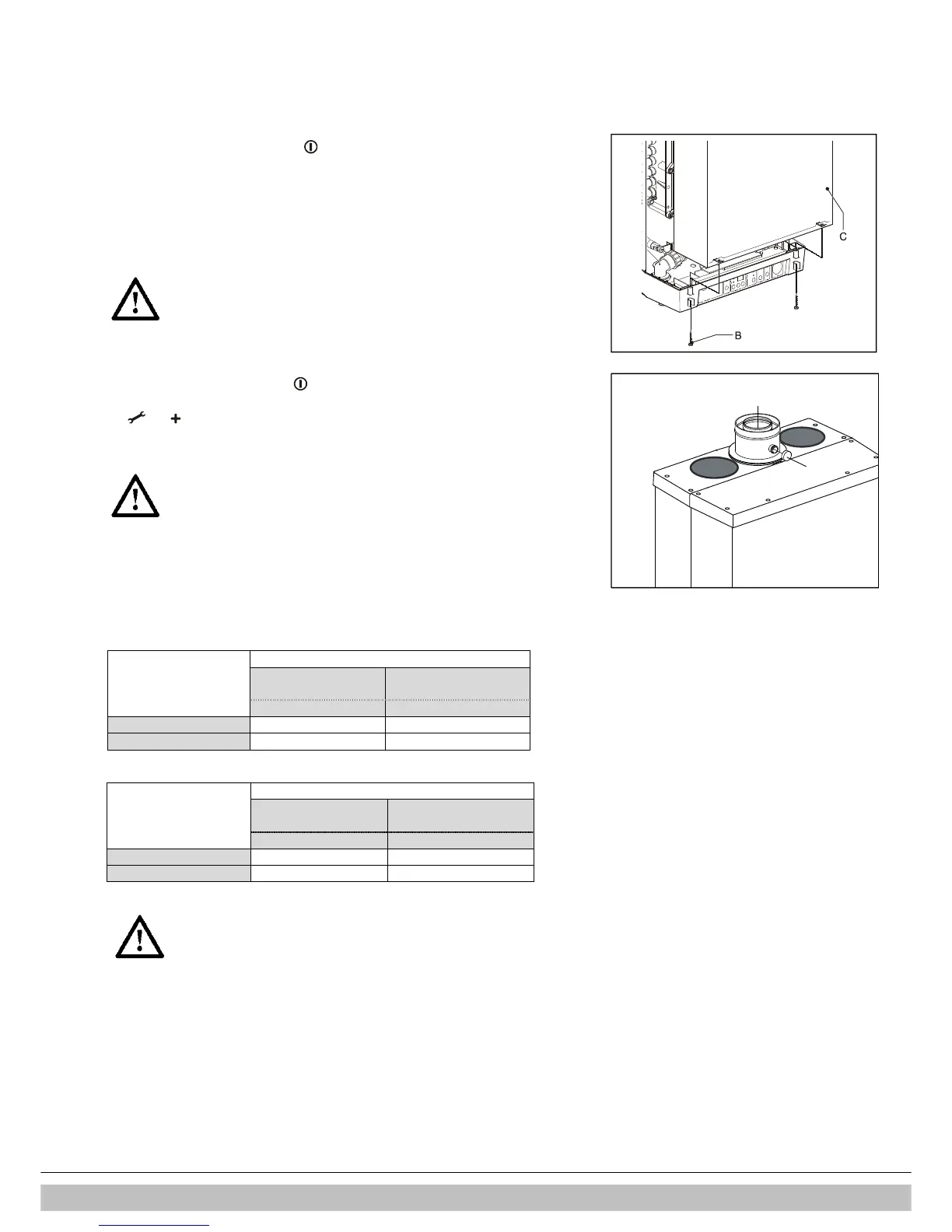
2. Remove the front panel by untightening the 2 screws.
3. Remove the cap X of the flue gas sampling point on the adapter.
4. Position the measuring probe or the flue gas analyser into the sampling point.
Important
• Ensure yourself that the analyser start up procedure has
been finalized before placing the probe.
• The probe needs to close the sampling point fully to ensure
an accurate measurement
• The end (tip) of the probe must be completely in the flue
gasses (in the middle of the flue pipe)
.
5. Switch the appliance on with the button .
6. Activate the test program for maximum output by simultaneously pressing the buttons
and twice. A capital H appears in service display.
Important
• Make sure a capital H is shown in the display to ensure the
appliance to run at maximum power.
7. Wait until the reading of the flue gas analyser is stable (minimal 3 minutes)
8. Note the measured value O
2
(H) or CO
2
(H)
O
2
(H) = measured O
2
value at maximum power
CO
2
(H) = Measured CO
2
value at maximum power
9. Check if the measured value is in accordance with the data noted in table 2a or 2b .
Table 2a: Limits O
2
(H) at maximum power (open casing)
Gas category
Limits Natural gas
G 20
Propane 3P
G31
O
2
[%] O
2
[%]
Maximum value 5.60 6.05
Minimum value 3.85 4.50
Tabel 2b: Limits CO
2
(H) at maximum power (open casing)
Limits
Gas category
Natural gas
G 20
Propane 3P
G31
CO
2
[%] CO
2
[%]
Maximum value 9.6 10.8
Minimum value 8.6 9.8
Important
• A deviation at maximum power can not be adjusted with the gas valve
setting. When the value measured at maximum power is without the
prescribed range the boiler has to be checked on gas tightness and
usage of the correct components, in particular the gas ring, the insert
and the fan.
10. Proceed performing the measurement on minimum output(see § 8.9.2).

 Loading...


