Intergas Heating Ltd
35
8.2 Settings through the service code
The burner controller of the appliance has been set in the factory according to the parameters of §
8.3. These parameters can only be changed with the service code. Proceed as follows to activate
the program memory:-
1. Set the appliance in the off mode using the On/Off key (
-
on the service display).
2. Simultaneously press the Service and Reset keys, until a
0
appears on the service and the
temperature displays.
3. Using the “+” and “-“ keys, set
15
(service code) on the temperature display.
4. Press the “Service” key to confirm the code and enter the desired parameter.
5. Set using the “Service” key the parameter to be set on the service display.
6. Set using the “+” and “-“ keys the parameter to the required value on the
temperature display.
7. After having entered all required changes, press the “Reset” key
until
P
appears on the service display.
8. Switch on the appliance again using the “On/Off” key.
The burner controller has now been reprogrammed.
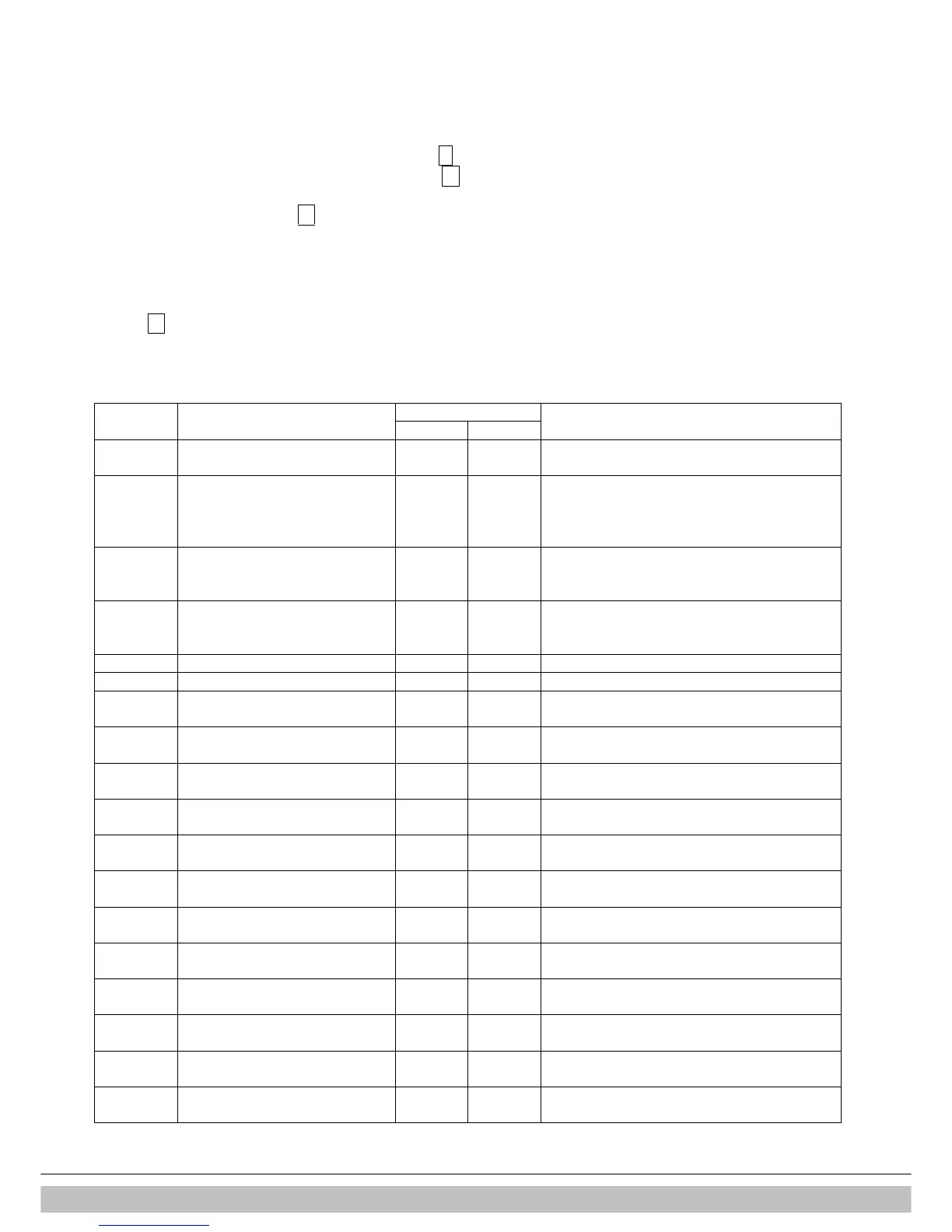
8.3 Parameters
Access to installer settings. The service code must
1 = heating only operation + indirect hot water tank
2 = hot water only operation
3 = heating only opration
1 = pump continuously active
2 = n/a
Setting range : value par. c – 90 % (Rapid 25)
Value par. c – 100 % (Rapid 32)
Max. power for modulating pump
Min. supply temperature of the
Setting range 10°C to 25°C (Weather
Max. value for the flow temperature
Min. outside temperature of the
Max. outside temperature of the
Setting range 15°C to 30°C (Weather
CH pump overrun time after CH
CH pump overrun time after heating
0 = confirmed during CH operation
1 = confirmed during hw operation (n/a)
0 = step modulation off during CH operation
1 = step modulation on during CH operation
Minimum power modulating pump
Minimum speed/ output DHW

 Loading...


