Intergas Heating Ltd 26
Flue system
6.5.1 Flue pipe and air supply
For connecting the boiler to a concentric flue system a special concentric flue
adapter has to be used. An adapter for connecting to a 60/100 flue system or
to a concentric 80/125 flue system can be ordered at Intergas Heating Ltd.
For the appropriate types see chapter 4.1 Accessories.
Note
Only use approved Intergas flue products with this boiler, which can be
sourced from the supplier of your boiler or Intergas stockist.
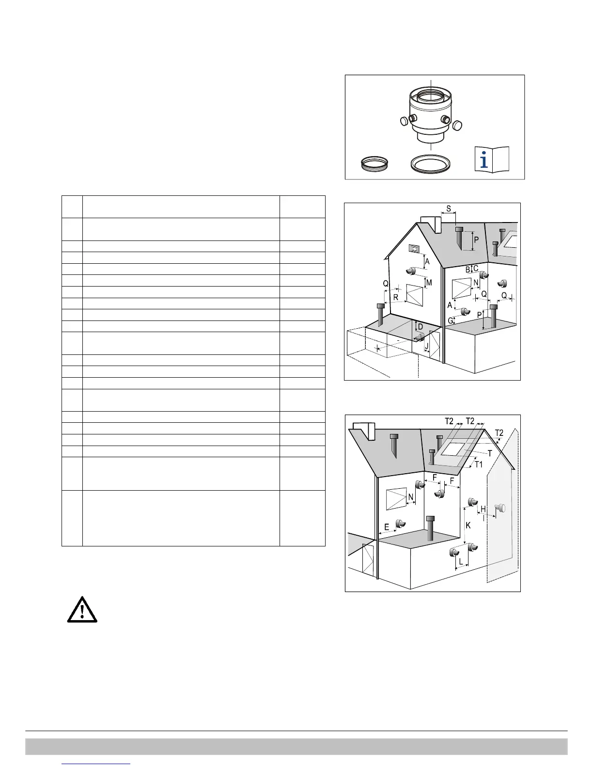
Terminal Position
Directly below an open able window or other opening
Below gutters, soil pipes or drain pipes
From vertical drain pipes and soil pip
From internal or external corners
Above ground, roof or balcony level
From a surface facing a terminal
From a terminal discharging towards another terminal
From an opening in a car port (e.g. door, window) into
Vertically from a terminal on the same wall
Horizontally from a terminal on the same wall
Above an opening, air brick, opening windows, etc.
Horizontally to an opening, air brick, opening
Above roof level (to base of terminal)
From adjacent wall to flue
From an adjacent opening window
From another roof terminal
facing a boundary it is recommended that an anti-
plume kit be fitted.
Terminals adjacent to windows or openings on
The flue should not penetrate this area.
Note
Intergas cannot be held responsible for atmospheric conditions when siting
flue terminals
Once the flue has been installed and the appliance
commissioned, installer should observe the plume
direction. Particular attention should be drawn to plume
vapour re-entering the boiler via the air intake. If this
occurs, it is highly possible the flue is fitted within a
negative pressure area and therefore a plume
management kit (PMK) must be fitted.

 Loading...


