Intermec EasyCoder PF2i, PF4i, and PF4i Compact Industrial—Service Manual 201
Chapter 14—Interfaces
Installation Instructions
• Switch off the printer and disconnect the power cord.
• Disconnect all communication cables.
• Remove the front/left-hand cover as described in Chapter 3.2.
• Remove any optional interface board or blind cover plate fi tted on the
rear plate.
• Remove any present EasyLAN Ethernet interface installed in the printer
including cables etc.
• Remove the present rear plate like this:
- Loosen but do not remove the two #T20 Torx screws that hold the
rear plate and the #T20 Torx screw that holds the rear bottom corner
of the CPU board.
- Carefully manipulate the rear plate out of the groove in the chassis.
Allow the CPU board to fl ex a little to be able to get the connectors
out of their slots.
• Install the rear plate included in the kit in reverse order and tighten all
three screws.
• Reinstall any optional interface board or blind cover plate previously
removed.
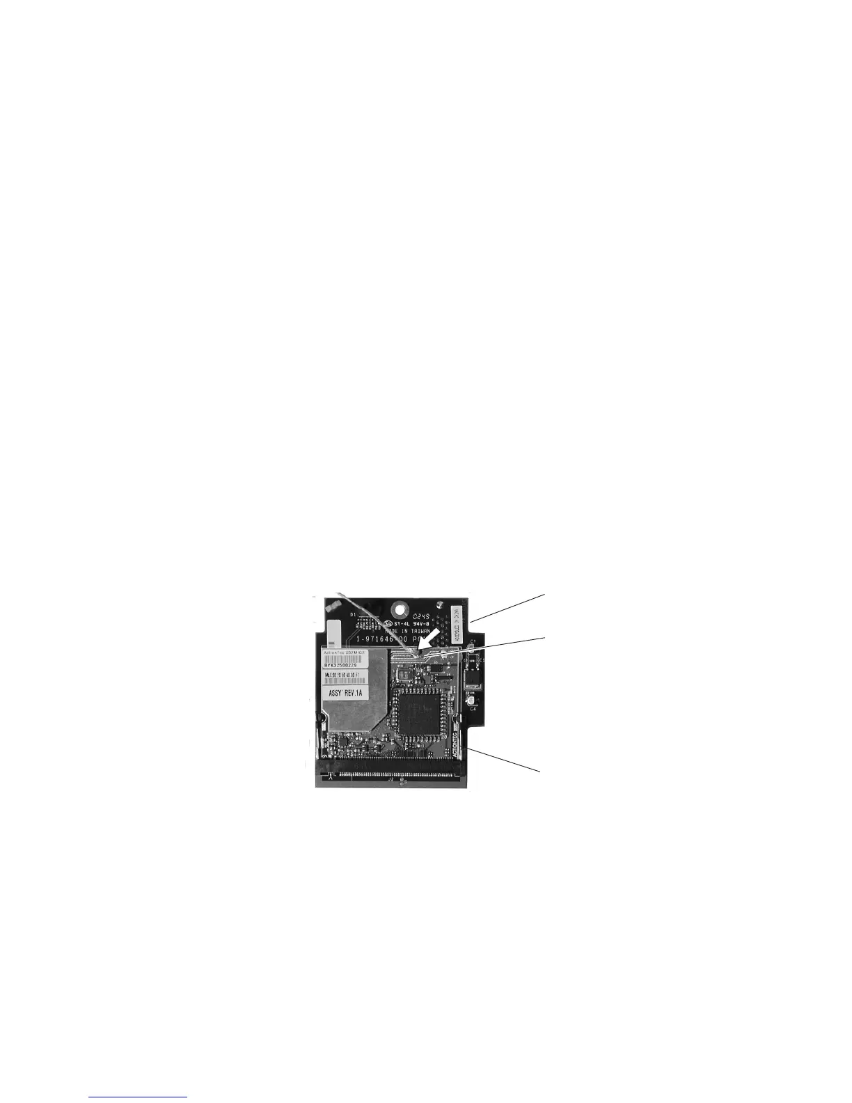
• Connect the antenna cable to the radio module, which is factory-fi tted
on the EasyLAN adapter board, as illustrated below. Support the upper
edge of the radio module with a fi nger while connecting the cable.
• Remove the #T20 Torx screw that holds the upper/front part of the
CPU board to the power supply unit and replace it with the hexagonal
spacer included in the kit. Keep the screw.
• Connect the EasyLAN adapter board to the PCI connector (J84) on the
CPU board so the hole in the board becomes aligned with the spacer
and secure the board with the #T20 Torx screw.
• Route the antenna cable over the SIMMs on the CPU board towards
the rear plate and secure it using the cable clips included in the kit.
One clip is factory-fi tted on the EasyLAN adapter board and the
other should be fi tted in the small hole at the top of the CPU board
immediately to the rear of the memory SIMM sockets.
Connect antenna
cable here
Radio module
Adapter board