18
4. In the allowable voltage range, the output power and current can not exceed the
rated output power and current in any situation.
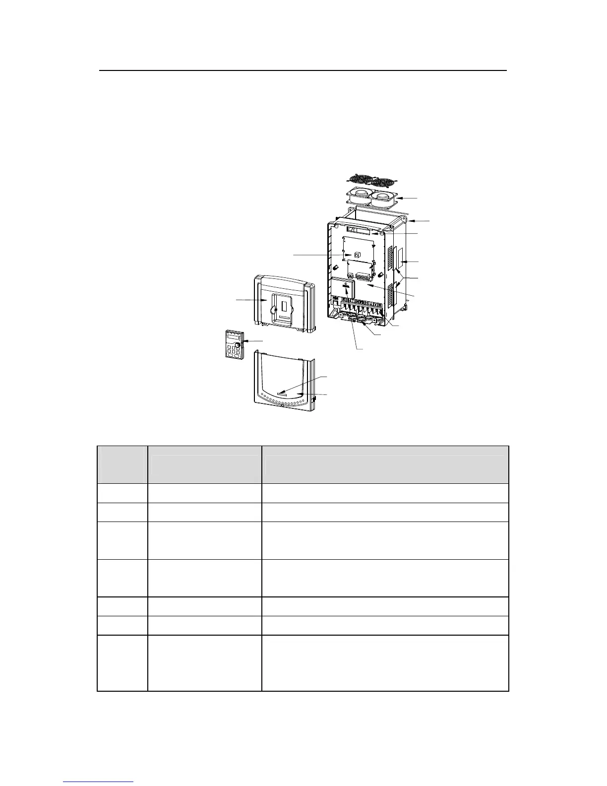
3.7 Structure diagram
Below is the layout figure of the inverter (take the inverter of 30kW as the example).
4
6
7
1
2
3
14
13
9
10
11
12
8
5
Fig 3-5 Product structure diagram
Serial
No.
Name Illustration
1 Keypad port Connect the keypad
2 Upper cover Protect the internal parts and components
3 Keypad
See Keypad Operation Procedure for detailed
information
4 Cooling fan
See Maintenance and Hardware Fault Diagnose for
detailed information
5 Wires port Connect to the control board and the drive board
6 Name plate See Product Overview for detailed information
7 Side cover
Optional part. The side cover will increase the
protective degree of the inverter. The internal
temperature of the inverter will increase, too, so it is