26
Note: Ensure the separation of the wind input and output channels in tilt installation for
avoiding mutual impact.
4.3 Standard wiring
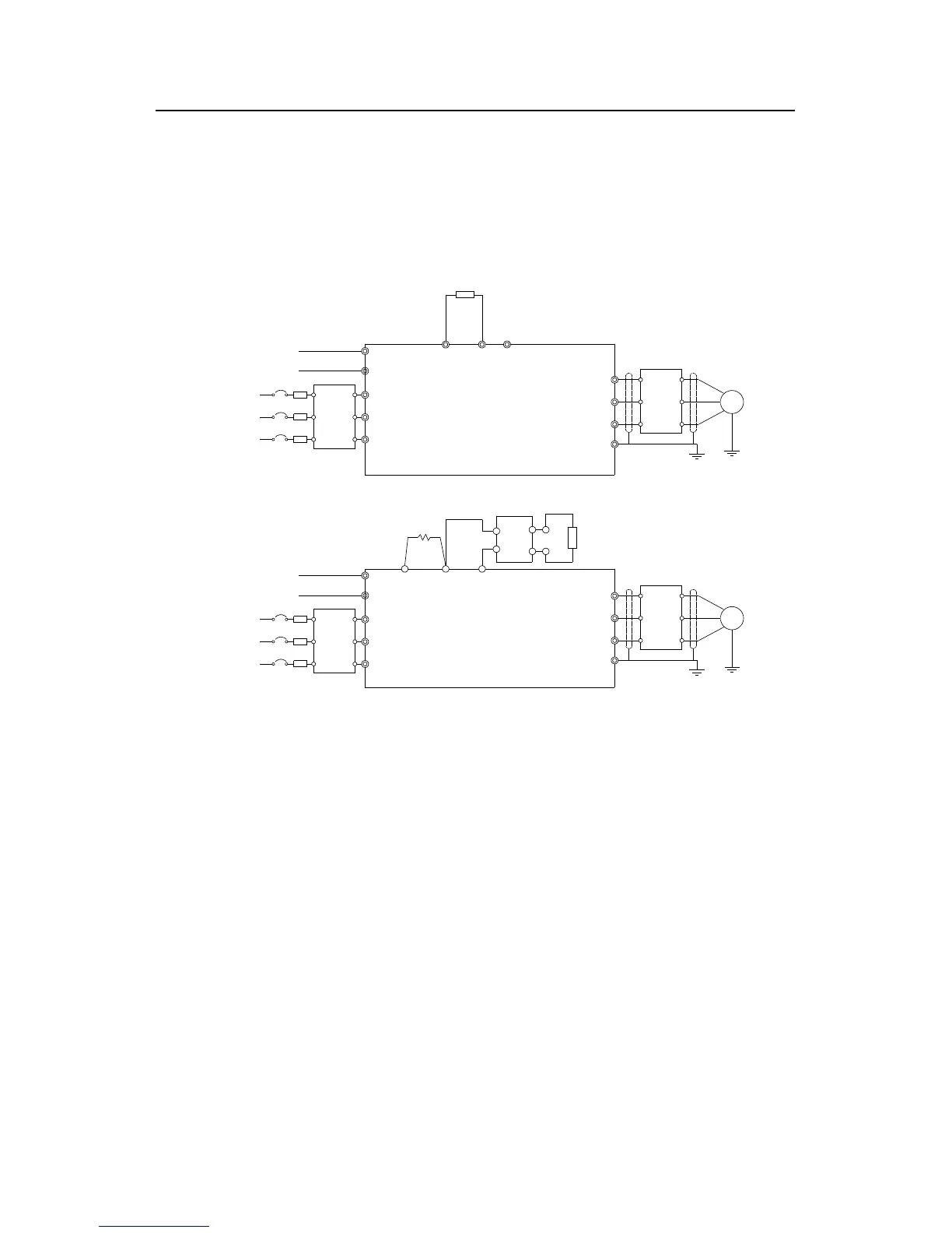
4.3.1 Wiring diagram of main circuit
R
S
T
W
V
U
PE
M
The inverters≤30kW
(+)
PB
3AC
380V±15%
50/60Hz
Braking resistor
Input
reactor
Input
filter
Fuse
A1
A2
Single phase 220V
optinal
(-)
R
S
T
W
V
U
PE
M
P1 (+)
DC reactor
(-)
A1
A2
DC-
DC+
Output
reactor
Output
filter
Braking resistor
Braking unit
Fuse
Input
reactor
Input
filter
Output
reactor
Output
filter
The inverters≥37kW
Diagram 4-7 Wring diagram of main circuit
Note:
The fuse, DC reactor, braking unit, braking resistor, input reactor, input filter, output
reactor, output filter are optional parts. Please refer to Peripheral Optional Parts for
detailed information.
A1 and A2 are optional parts.
P1 and (+) are short circuited in factory, if need to connect with the DC rector, please
remove the contact tag between P1 and (+).