236
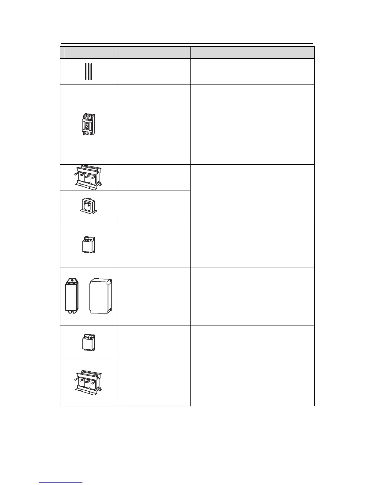
Pictures Name Descriptions
Cables Device to transfer the electronic signals
Breaker
Prevent from electric shock and protect the
power supply and the cables system from
overcurrent when short circuits occur.
(Please select the breaker with the
function of reducing high order harmonic
and the rated sensitive current to 1 inverter
should be above 30mA).
Input reactor
DC reactor
This device is used to improve the power
factor of the input side of the inverter and
control the higher harmonic current.
The inverter above 37kW (including 37kW)
can be connected with DC reactor.
Input filter
Control the electromagnetic interference
generated from the inverter, please install
close to the input terminal side of the
inverter.
or
Shorten the DEC time
The inverters below 30kW(including 30kW)
only need braking resistors and the
inverters above 37kW(including 37 kW)
need braking units
Output filter
Control the interference from the output
side of the inverter and please install close
to the output terminals of the inverter.
Output reactor
Prolong the effective transimiting distance
of the inverter to control the sudden high
voltage when switchiong on/off the IGBT of
the inverter.
C.3 Power supply
Please refer to Electronical Installation.