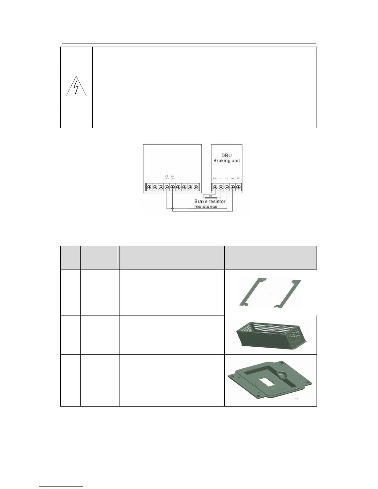
The inverters above 37kW (including 370kW) only needs external
braking units.
(+), (-) are the wiring terminals of the braking units.
The wiring length between the (+),(-) terminals of the inverter and the
(+),(-) terminals of the braking units should be no more than 5m,and the
distributing length among BR1 and BR2 and the braking resistor
terminals should be no more than 10m.
Signal installation is as below:
C.9 Other optional parts
No.
Optional
part
Instruction
Picture
1
Flange
installation
braket
Needed for the flange installation of
1.5~30kW inverters
Not needed for the flange installation
of 37~200kW inverters
2
Installation
base
Optinal for 220~315kW inverters
A input AC/DC reactor and output
AC reactor can be put in the base.
3
Installation
braket
Use the screw or installation braket
to fix the external keypad.
Optinal for 1.5~30kW iverters ans
standard for 37~500kW inverters

 Loading...


