5.1 What this chapter contains
This chapter contains following operation:
• Buttons, indicating lights and the screen as well as the methods to inspect, modify and
set function codes by keypad
• Start-up
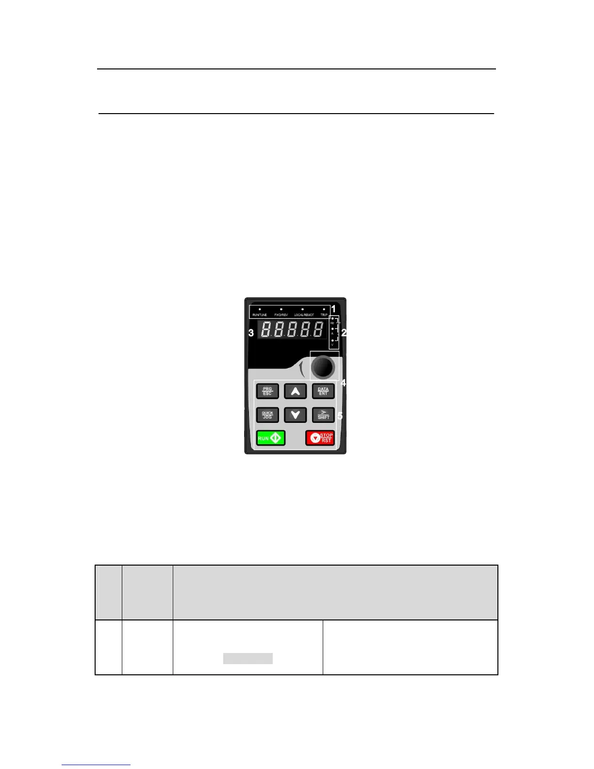
5.2 Keypad
The keypad is used to control Goodrive200 series inverters, read the state data and adjust
parameters.
Fig 5-1 Keypad
Note: Our company provides standard LED keypad, but the user can select optional
LCD keypad if needed. The LCD keypad supports several languages, parmeters copy,
high-definition display and its installation dimension is compatible with the LED.
Use strew or installation braket to fix the external keypad. The inverters of 1.5~30kW
have standard braket, while the inverters of 37~500kW have optinal braket.
Seri
al
No.
RUN/TUNE
LED off means that the inverter is in
the stopping state; LED blinking means
the inverter is in the parameter