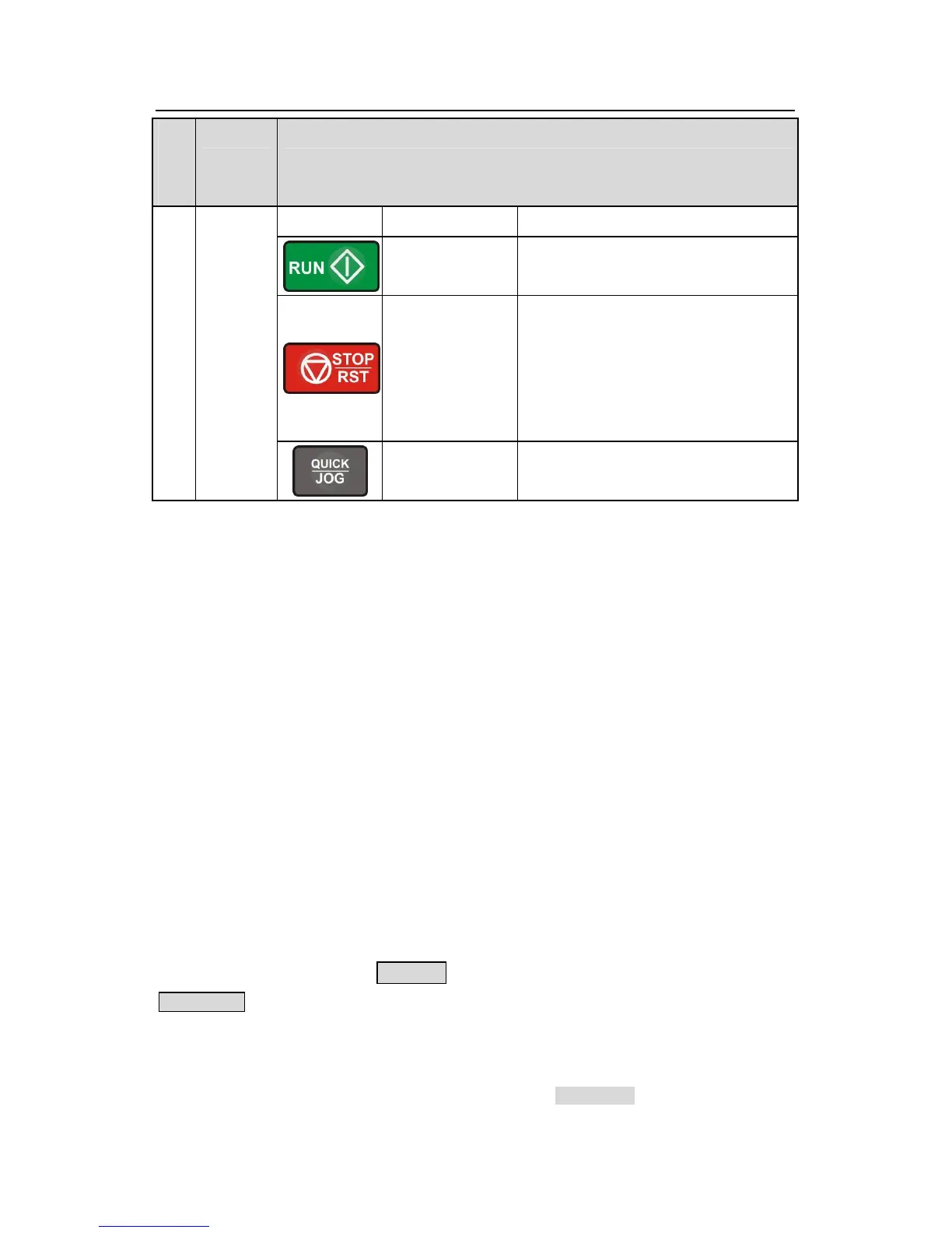
Stop/
Reset key
This key is used to stop in running
state and it is limited by function code
P07.04
This key is used to reset all control
modes in the fault alarm state
Quick key
The function of this key is confirmed by
function code P07.02.
5.3 Keypad displaying
The keypad displaying state of Goodrive200 series inverters is divided into stopping state
parameter, running state parameter, function code parameter editing state and fault alarm
state and so on.
5.3.1 Displayed state of stopping parameter
When the inverter is in the stopping state, the keypad will display stopping parameters which
is shown in figure 5-2.
In the stopping state, various kinds of parameters can be displayed. Select the parameters
to be displayed or not by P07.07. See the instructions of P07.07 for the detailed definition of
each bit.
In the stopping state, there are 14 stopping parameters can be selected to be displayed or
not. They are: set frequency, bus voltage, input terminals state, output terminals state, PID
reference, PID feedback, torque set value, AI1, AI2, AI3, HDI, PLC and the current step of
multi-step speeds, pulse counting value, length value. P07.07 can select the parameter to be
displayed or not by bit and 》 /SHIFT can shift the parameters form left to right,
QUICK/JOG(P07.02=2) can shift the parameters form right to left.
5.3.2 Displayed state of running parameters
After the inverter receives valid running commands, the inverter will enter into the running
state and the keypad will display the running parameters. RUN/TUNE LED on the keypad is