36
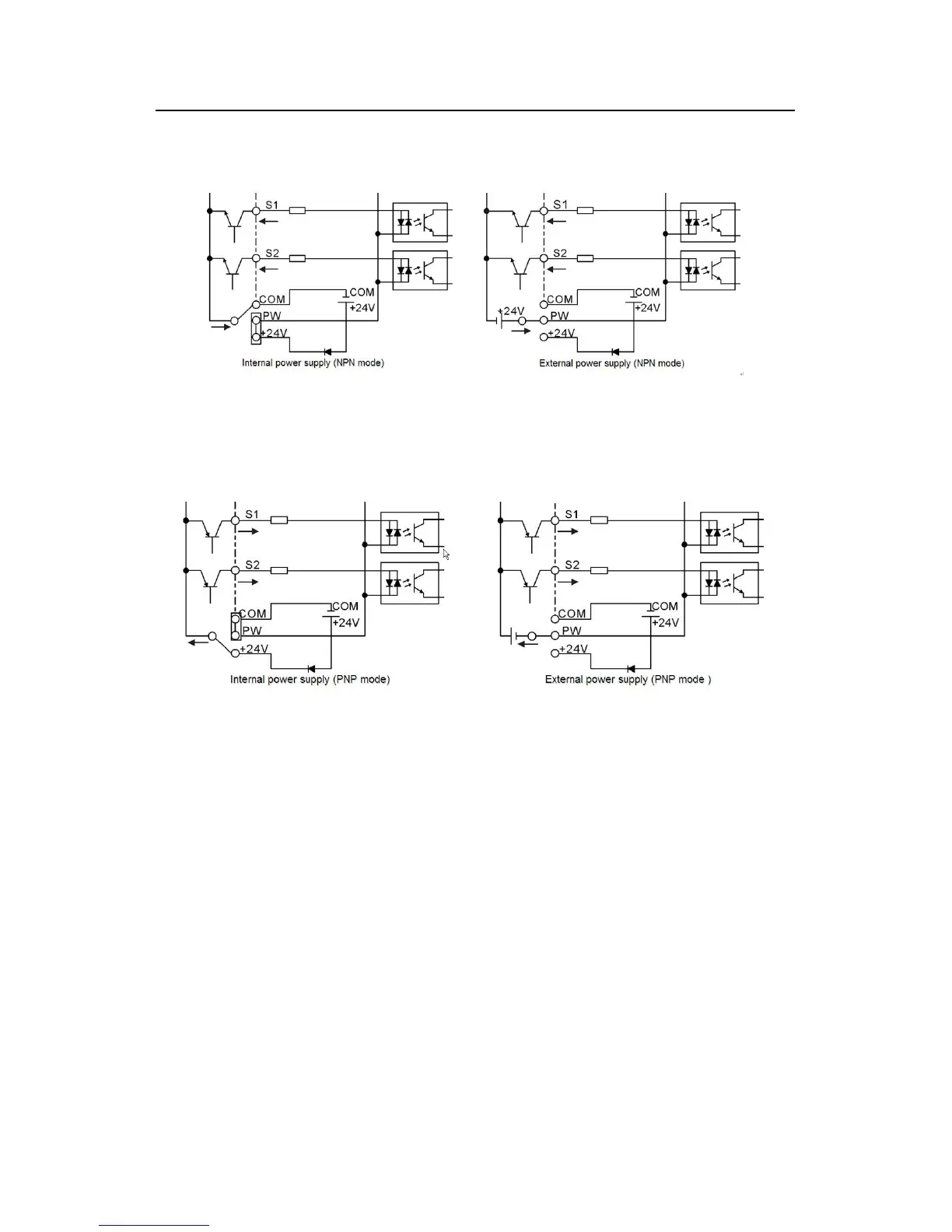
If the signal is from NPN transistor, please set the U-shaped contact tag between +24V and
PW as below according to the used power supply.
Fig 4-22 NPN modes
If the signal is from PNP transistor, please set the U-shaped contact tag as below according
to the used power supply.
Fig 4-23 PNP modes
4.4 Layout protection
4.4.1 Protecting the inverter and input power cable in short-circuit situations
Protect the inverter and input power cable in short circuit situations and against thermal
overload.
Arrange the protection according to the following guidelines.