43
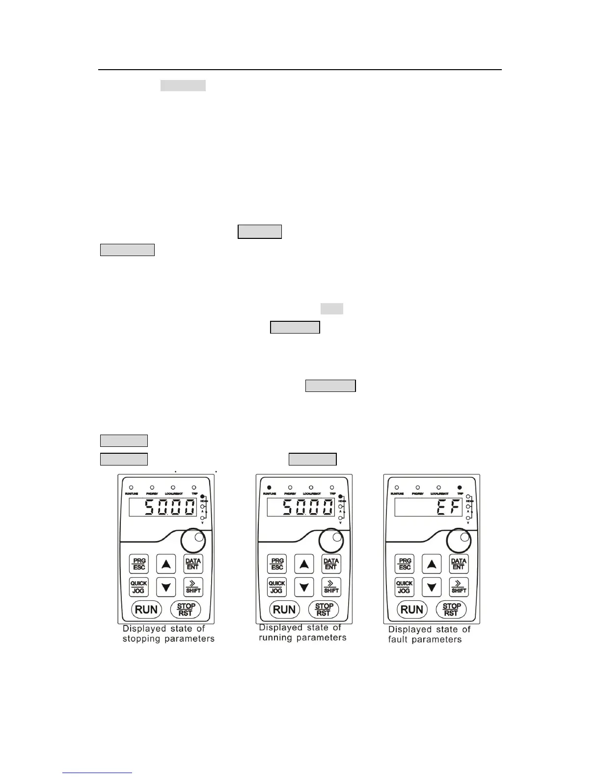
on, while the FWD/REV is determined by the current running direction which is shown as
figure 5-2.
In the running state, there are 23 parameters can be selected to be displayed or not. They
are: running frequency, set frequency, bus voltage, output voltage, output torque, PID
reference, PID feedback, input terminals state, output terminals state, torque set value,
length value, PLC and the current step of multi-step speeds, pulse counting value, AI1, AI2,
AI3, HDI, percentage of motor overload, percentage of inverter overload, ramp reference
value, linear speed, AC input current. P07.05 and P07.06 can select the parameter to be
displayed or not by bit and 》 /SHIFT can shift the parameters form left to right,
QUICK/JOG(P07.02=2) can shift the parameters from right to left.
5.3.3 Displayed state of fault
If the inverter detects the fault signal, it will enter into the fault pre-alarm displaying state. The
keypad will display the fault code by flicking. The TRIP LED on the keypad is on, and the
fault reset can be operated by theSTOP/RST on the keypad, control terminals or
communication commands.
5.3.4 Displayed state of function codes editing
In the state of stopping, running or fault, press PRG/ESC to enter into the editing state (if
there is a password, see P07.00 ).The editing state is displayed on two classes of menu, and
the order is: function code group/function code number→function code parameter, press
DATA/ENT into the displayed state of function parameter. On this state, you can press
DATA/ENT to save the parameters or press PRG/ESC to retreat.
Fig 5-2 Displayed state