248
The cousumped power of the
braking resistor
Type
Braking unit
type
100% of
braking
rate
(Ω)
10%
braking
GD200-400G-4
DBU100H-320-4
GD200-500G-4
Two
DBU100H-400-4
Never use a brake resistor with a resistance below the minimum value
specified for the particular drive. The drive and the internal chopper are
not able to handle the overcurrent caused by the low resistance.
Increase the power of the braking resistor properly in the frequent
braking situation (the frequency usage ratio is more than 10%).
C.8.2 Select the brake resistor cables
Use a shielded cable to the resistor cable.
C.8.3 Place the brake resistor
Install all resistors in a place where they will cool.
The materials near the brake resistor must be non-flammable. The
surface temperature of the resistor is high. Air flowing from the resistor
is of hundreds of degrees Celsius. Protect the resistor against contact.
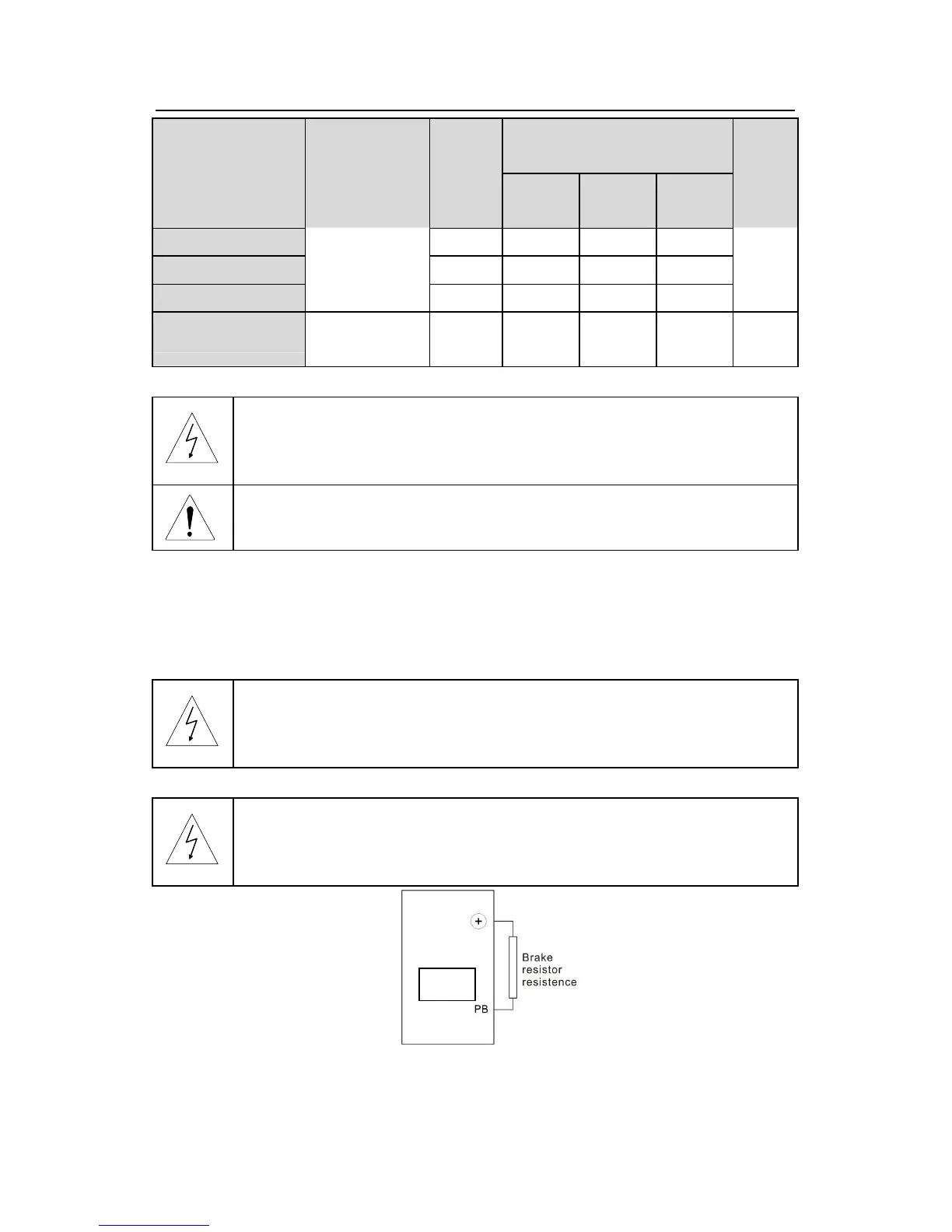
Installation of the braking resistor:
The inverters below30kW (including 30kW) only needs external braking
resistors.
PB and(+)are the wiring terminals of the braking resistors.
Installation of braking units: