Goodrive35 inverters Basic operation instruction
198
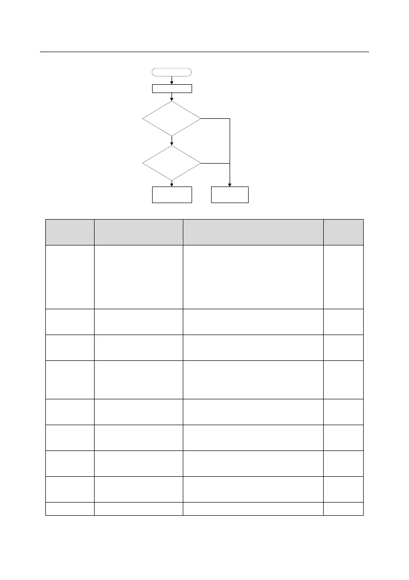
3. The starting logic figure of starting after the automatic fault reset.
The inverter fault
In running
The fault reset times of the
inverter<P08.28
The interval time of the fault
reset time of the inverter
>P08.29
Fault reset and the
inverter starts to run.
Display the fault code
and the inverter stops
N
N
Y
Y
Relative parameters list:
Detailed instruction of parameters
0:Keypad running command(LED off)
1:Terminal running command channel
(LED flickering)
2:Communication running command
channel (LED on)
0:Start-up directly
1:Start-up after DC braking
2: Start-up after rotation speed tracking 1
Starting frequency of
direct start
Retention time of the
starting frequency
The braking current before
starting
The braking time before
starting

 Loading...


