Goodrive35 inverters Appendix A
302
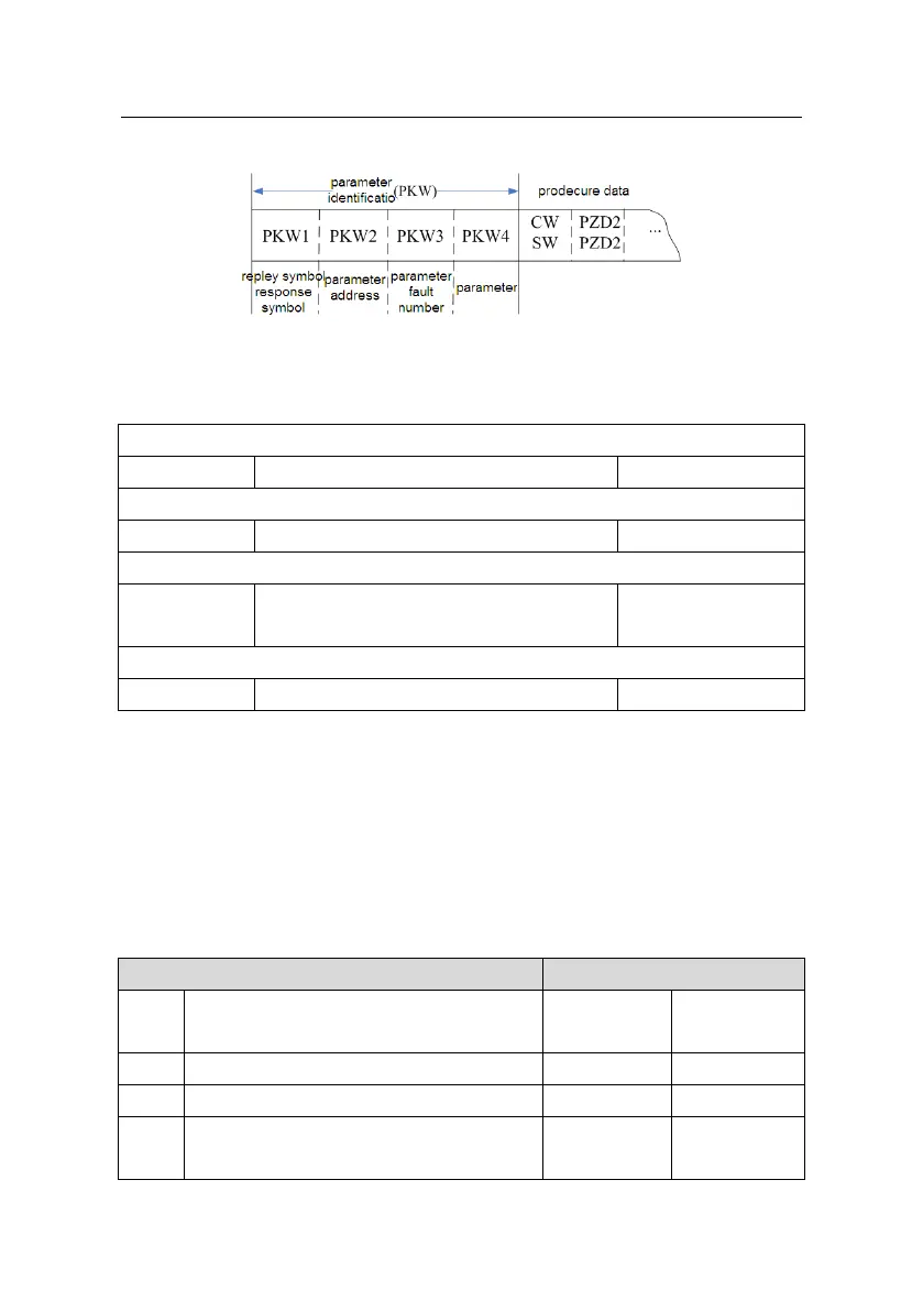
Structure of PKW area:
Parameter identification zone
In the process of periodic PROFIBUS/CANOPEN-DP communication, PKW area is
composed of four words (16 bit), each word is defined as follows:
The first word PKW1 (16 bit)
Task or response identification marks
The second word PKW2 (16 bit)
The third word PKW3 (16 bit)
Parameter value (high word) or return error
code value
The fourth word PKW4 (16 bit)
Parameter value (low word)
Note: If the master requests one parameter value, the value of PKW3 and PKW4 will not be
valid.
Task requests and responses
When passing data to slave machine, master machine use request label while slave
machine use response label to positive or negative confirmation. Table 5.5 and Table 5.6 list
the request/response functional.
The definition of task logo PKW1 is as follows:
Definition of task logo PKW1
Request label (From master to slave)
Modification parameter value (one word)
[only change RAM]
 Loading...