Goodrive270 series VFD for fan and pump Basic operation guidelines
-116-
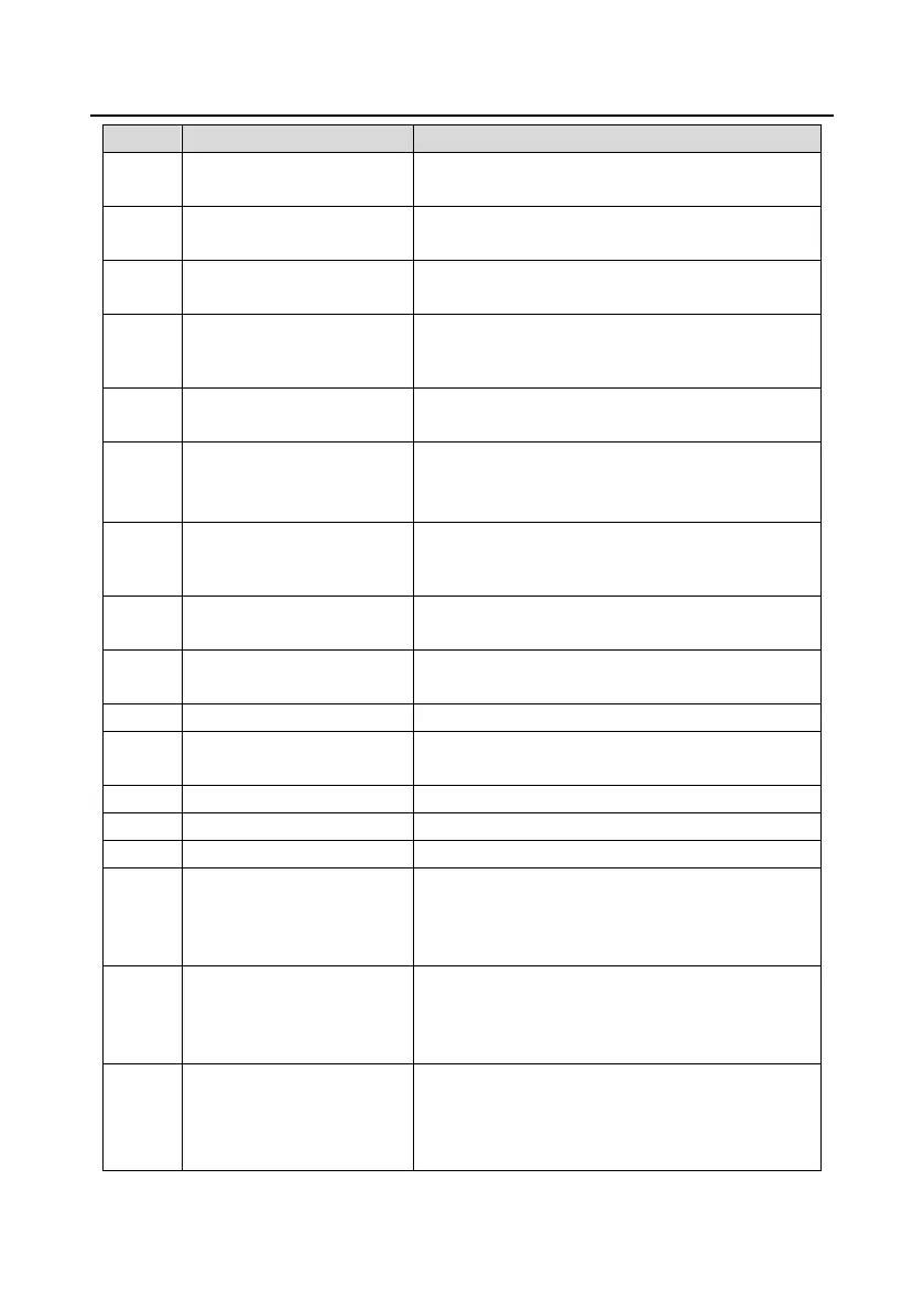
The ON signal is output when the VFD output
frequency and reference frequency are both zero.
Upper limit frequency
reached
The ON signal is output when the running frequency
reaches the upper limit frequency.
Lower limit frequency
reached
The ON signal is output when the running frequency
reaches the lower limit frequency.
The ON signal is output when main circuit and
control circuit powers are established, the protection
functions do not act, and the VFD is ready to run.
The ON signal is output when the VFD is in
pre-exciting.
Output ON signal after the pre-alarm time elapsed
based on the pre-alarm threshold; see
P11.08–P11.10 for details.
The ON signal is output after the pre-alarm time
elapsed based on the pre-alarm threshold. For
details, see the descriptions for P11.11–P11.12.
Simple PLC stage
completed
When the present state of the simple PLC is
completed, it outputs a signal.
Simple PLC cycle
completed
When a single cycle of the simple PLC is completed,
it outputs a signal.
Set counting value reached
Designated counting value
reached
Modbus communication
virtual terminal output
A signal is output based on the value set through
Modbus communication. When the value is 1, the
ON signal is output; when the value is 0, the OFF
signal is output.
POROFIBUS/CANopen
communication virtual
terminal output
A signal is output based on the value set through
PROFIBUS/CANopen communication. When the
value is 1, the ON signal is output; when the value is
0, the OFF signal is output.
Ethernet communication
virtual terminal output
A signal is output based on the value set through
Ethernet communication. When the value is 1, the
ON signal is output; when the value is 0, the OFF
signal is output.

 Loading...