EasyManuals Logo

INVT Goodrive270 Series User Manual

INVT Goodrive270 Series
372 pages
To Next Page IconTo Next Page
To Previous Page IconTo Previous Page
Page #138 background imageLoading...
Page #138 background image
Goodrive270 series VFD for fan and pump Basic operation guidelines
-128-
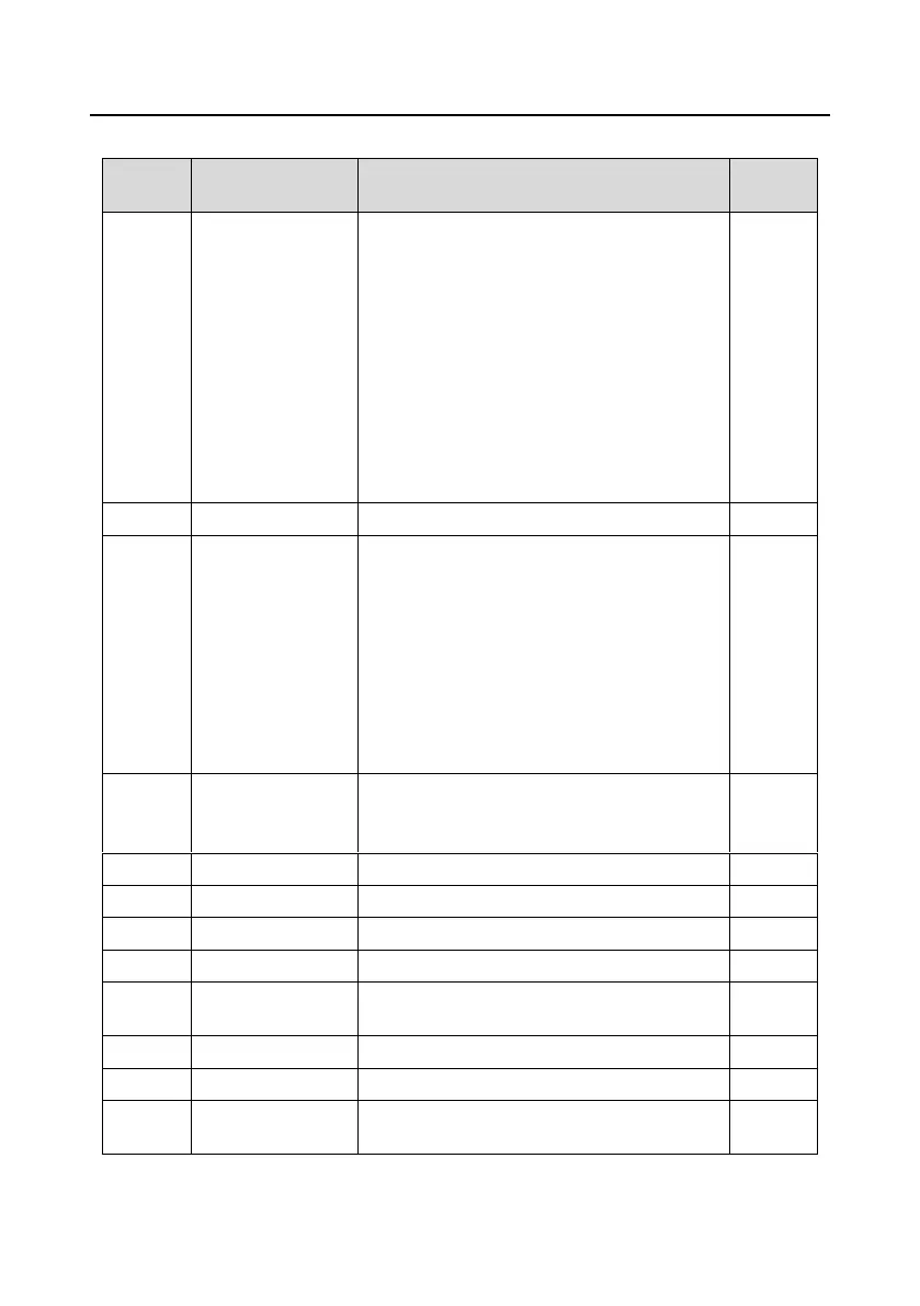
Related parameter list:
Function
code
Name
Description
Default
P09.00
PID reference source
0: Set by P09.01
1: AI1
2: AI2
3: AI3
4: High-speed pulse HDIA
5: Multi-step running
6: Modbus communication
7: PROFIBUS/CANopen communication
8: Ethernet communication
9: Reserved
10: PROFINET communication
0
P09.01
PID digital setting
-100.0%–100.0%
0.0%
P09.02
PID feedback source
0: AI1
1: AI2
2: AI3
3: High-speed pulse HDIA
4: Modbus communication
5: PROFIBUS/CANopen communication
6: Ethernet communication
7: Reserved
8: PROFINET communication
0
P09.03
PID output
characteristics
selection
0: PID output is positive.
1: PID output is negative.
0
P09.04
Proportional gain (Kp)
0.00–100.00
1.80
P09.05
Integral time (Ti)
0.01–10.00s
0.90s
P09.06
Differential time (Td)
0.00–10.00s
0.00s
P09.07
Sampling cycle (T)
0.000–10.000s
0.100s
P09.08
PID control deviation
limit
0.0–100.0%
0.0%
P09.09
PID output upper limit
P09.10–100.0% (Max. frequency or voltage)
100.0%
P09.10
PID output lower limit
-100.0%–P09.09 (Max. frequency or voltage)
0.0%
P09.11
Feedback offline
detection value
0.0–100.0%
0.0%

Table of Contents

Questions and Answers:

Question and Answer IconNeed help?

Do you have a question about the INVT Goodrive270 Series and is the answer not in the manual?

INVT Goodrive270 Series Specifications

General IconGeneral
BrandINVT
ModelGoodrive270 Series
CategoryWater Pump
LanguageEnglish

Related product manuals