Goodrive270 series VFD for fan and pump Function parameter list
-156-
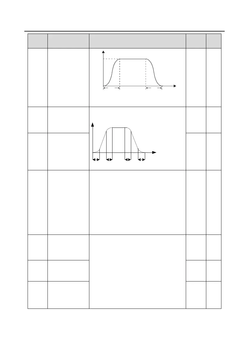
Output frequency f
Time t
fmax
t1 t2
Note: If mode 1 is selected, set P01.06, P01.07,
P01.27, and P01.28 accordingly.
Time of starting
segment of ACC S
curve
The curvature of S curve is determined by the
ACC range and ACC/DEC time.
Output frequency f
Time t
t1 t2 t3 t4
t1=P01.06
t2=P01.07
t3=P01.27
t4=P01.28
Time of ending
segment of ACC S
curve
0: Decelerate to stop. After a stop command
takes effect, the VFD lowers output frequency
based on the DEC mode and the defined DEC
time; after the frequency drops to the stop speed
(P01.15), the VFD stops.
1: Coast to stop. After a stop command takes
effect, the VFD stops output immediately; and
the load coasts to stop according to mechanical
inertia.
Starting frequency
of DC braking for
stop
Starting frequency of DC braking for stop: During
the deceleration to stop, the VFD starts DC
braking for stop when running frequency
reaches the starting frequency determined by
P01.09.
Wait time before DC braking: The VFD blocks
the output before starting DC braking. After this
wait time, DC braking is started so as to prevent
overcurrent caused by DC braking at high
speed.
DC braking current
for stop

 Loading...