Goodrive270 series VFD for fan and pump Function parameter list
-157-
DC braking current for stop: It indicates the
applied DC braking energy. Stronger current
indicates greater DC braking effect.
DC braking time for stop: It indicates the hold
time of DC braking. If the time is 0, DC braking is
invalid, and the VFD decelerates to stop within
the specified time.
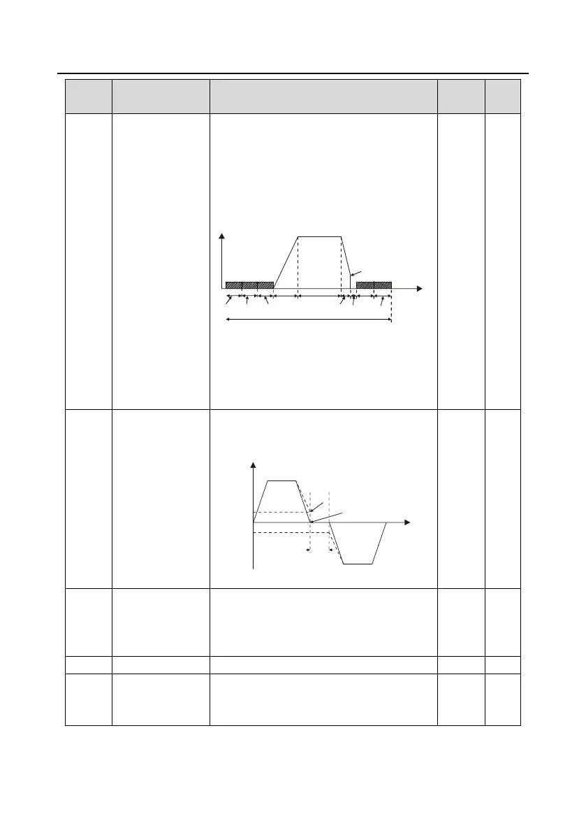
P01.04
ACC
P01.30
P01.23
Constant speed
In running
DEC
P01.10
P01.31
P01.12
P01.09
Time t
P01.09 setting range: 0.00Hz–P00.03 (Max.
output frequency)
P01.10 setting range: 0.00–30.00s
P01.11 setting range: 0.0–100.0%
P01.12 setting range: 0.0–50.0s
FWD/REV running
deadzone time
This function code indicates the transition time
specified in P01.14 during FWD/REV rotation
switching. See the following figure:
Output frequency f
Forward
Reverse
Deadzone
time
Time t
Starting
frequency
Switch over after
zero frequency
Switch over after
starting frequency
Setting range: 0.0–3600.0s
FWD/REV running
switching mode
0: Switch at zero frequency
1: Switch at the starting frequency
2: Switch after the speed reaches the stop
speed with a delay
Stop speed
detection mode
0: Detect by the set speed (unique in space
voltage vector control mode)
1: Detect by the feedback speed

 Loading...