Goodrive270 series VFD for fan and pump Function parameter list
-189-
63: Control variable-frequency circulation motor G
64: Control variable-frequency circulation motor H
Output terminal
polarity selection
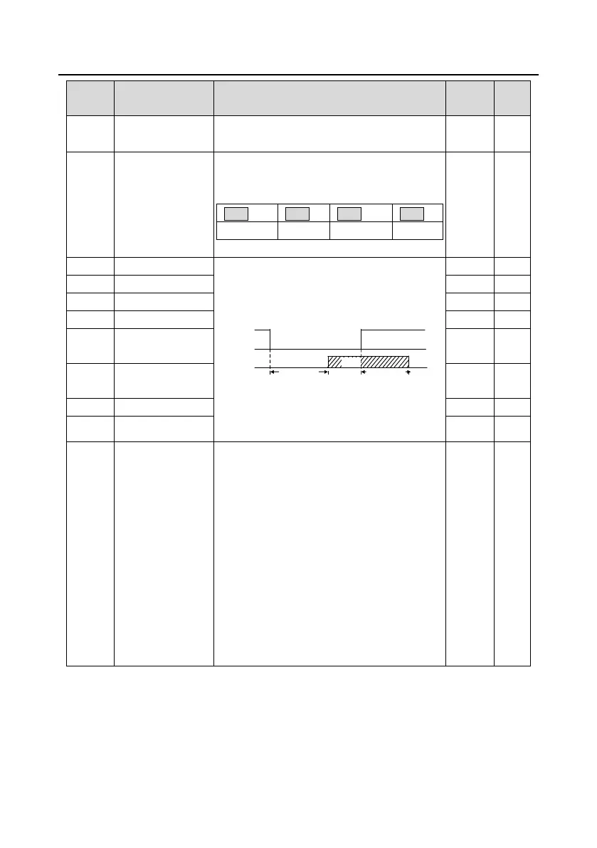
Used to set the polarity of output terminals.
When a bit is 0, the terminal is positive;
when a bit is 1, the terminal is negative.
Used to specify the delay time corresponding to
the electrical level changes when the
programmable output terminals switch on or
switch off.
Y electric level
Y valid
Invalid
Switch on
delay
invalid
Valid
Switch off
delay
Setting range: 0.000–50.000s
Note: P06.08 and P06.09 are valid only when
P06.00=1.
0: Running frequency (0–Max. output frequency)
1: Set frequency (0–Max. output frequency)
2: Ramp reference frequency (0–Max. output
frequency)
3: Rotational speed (0–Speed corresponding to
max. output frequency)
4: Output (0–Twice the inverter unit rated
current)
5: Output current (0–Twice the motor rated
current)
6: Output (0–1.5 times the inverter unit rated
voltage)
7: Output power (0–Twice the motor rated
power)

 Loading...