Goodrive270 series VFD for fan and pump Function parameter list
-202-
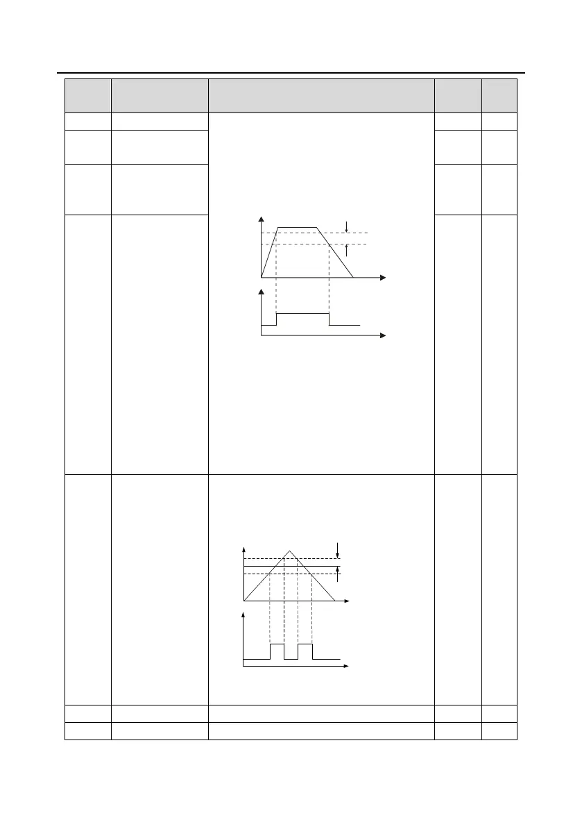
the multifunction digital output terminal
continuously outputs the signal of "Frequency
level detection FDT". The signal is invalid only
when the output frequency decreases to a value
lower than the frequency corresponding to (FDT
electrical level—FDT lagging detection value).
Time t
Output frequency f
FDT level
FDT lag
Y1,
RO1, RO2
Time t
P08.32 setting range: 0.00Hz–P00.03 (Max.
output frequency)
P08.33 setting range: 0.0–100.0% (FDT1
electrical level)
P08.34 setting range: 0.00Hz–P00.03 (Max.
output frequency)
P08.35 setting range: 0.0–100.0% (FDT2
electrical level)
FDT1 lagging
detection value
FDT2 electrical
level detection
value
FDT2 lagging
detection value
Detection value for
frequency being
reached
When the output frequency is within the
detection range, the multifunction digital output
terminal outputs the signal of "Frequency
reached".
Y1,
RO1, RO2
Output frequency
Set
frequency
Detection amplitude
Time t
Time t
Setting range: 0.00Hz–P00.03 (Max. output
frequency)

 Loading...