Do you have a question about the ISCO 4230 and is the answer not in the manual?
Explains how the bubbler system, pressure transducer, and drift compensation work.
Presents the physical and electrical specifications of the 4230 Flow Meter.
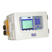
Lists and describes the physical controls, indicators, and connectors on the 4230.
Details the various power sources for the 4230 Flow Meter.
Explains the bubble rate adjustment valve and its function.
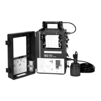
Covers mounting options, carrying handle, and location considerations.
Details the bubble line types, installation, and maintenance.
Explains analog outputs for process control equipment via 4-20 mA current loops.
Covers displaying, recording, and storing data from parameter sensors.
Explains the pH probe's function, measurement, and calibration.
Details the process for calibrating the pH probe using buffer solutions.
Details the D.O. probe's function, operation, and maintenance.
Describes the YSI 600 Sonde for multi-parameter water quality measurement.
Provides troubleshooting steps and guidance on servicing the flow meter.
Explains how to locate and replace fuses in the flow meter.
Details the components and operation of the bubbler system.
Outlines initial steps for troubleshooting unit problems.
Provides safety precautions for servicing CMOS circuitry and handling static electricity.
Highlights the risks of static electricity to CMOS circuitry and precautions.
Guides on updating the instrument's software using FLASH UPDATE.
Worksheet for configuring flow conversion settings, including weir, flume, equation, and Manning types.
Worksheet for adjusting parameters like Level, pH, D.O., and YSI 600 calibration.
Worksheet for configuring sampler pacing based on flow pulses or conditions.
Worksheet for configuring sampler enable modes and conditions.
Worksheet for configuring alarm dialout settings, including phone numbers and conditions.
Worksheet for configuring printer settings like speed and data lines.
Provides general safety advice and procedures for working in manholes and sewers.
Discusses common hazardous gases in sewers and their effects.
Provides a table detailing hazardous gases, their properties, and safety testing methods.
| Brand | ISCO |
|---|---|
| Model | 4230 |
| Category | Measuring Instruments |
| Language | English |