4230 Flow Meter
Section 1 Introduction
1-3
1.3 Operating Principles When measuring flow rate, the 4230 is used with a primary mea-
suring device (typically a weir or a flume) or other open channel
flow arrangement where a known relationship exists between
level and flow rate. The level measuring device is a bubbler
which measures the liquid level in the flow stream. The flow
meter electronically converts the level reading into a
properly-scaled flow rate value. The flow meter also provides
standard or optional flow-related output signals to be used for:
• Flow-proportional sampler pacing and enabling
• Recording flow rate information on an external
printer/plotter or circular chart recorder
• Data transfer through a modem
• Control of a 4-20 mA device
• Data transfer by a laptop computer
The flow meter contains microprocessor-controlled circuitry to
calculate level and flow rate from the signals produced by the
pressure transducer, store the program you entered, and operate
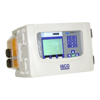
the display and the internal printer. An alphanumeric liquid
crystal display (LCD) is provided to show current total flow, level,
and flow rate, and to prompt you in programming the flow meter
during setup or subsequent program changes. An internal
printer provides a “hard copy” printout of the information com-
puted by the flow meter, plots level or flow rate, and generates
reports. Connectors for other equipment used with the 4230 are
arranged vertically on the right side of the flow meter case.
1.3.1 Operation of the
Bubbler System
The bubbler system, used by the 4230 to sense level in the flow
stream, works as follows: A small compressor pumps air into a
reservoir. This air is released slowly by a needle valve into a
bubble line, a length of small diameter flexible tubing. The other
end of this tube is submerged in the flow stream. Inside the flow
meter, the bubble line also connects to one side of a differential
pressure transducer. As air is released slowly into the bubble line
by the needle valve, pressure builds inside the line to force the
air out of the line into the flow stream. When there is enough
pressure to counteract the hydrostatic pressure of the flow
stream, a bubble will be forced from the end of the line. The
amount of pressure required to force the bubble from the end of
the line is directly dependent on the hydrostatic pressure of the
flow stream over the end of the bubble line. The pressure trans-
ducer inside the flow meter senses this pressure and converts it
into an electrical signal that the 4230 converts into level. From
the measured level detected by the bubbler and consulting
lookup tables for the primary device you are using, the flow
meter then calculates flow rate and total flow.
1.3.2 Pressure Transducer
Operation
The differential pressure transducer used with the bubbler con-
tains a resistance bridge on a silicon diaphragm. Pressure
against one side of this diaphragm causes it to flex slightly. This
flexing causes the resistors on one side of the bridge to stretch
slightly. At the same time the resistors on the other side of the
bridge compress slightly. The result is an unbalance in the