4230 Flow Meter
Section 5 Maintenance and Service
5-13
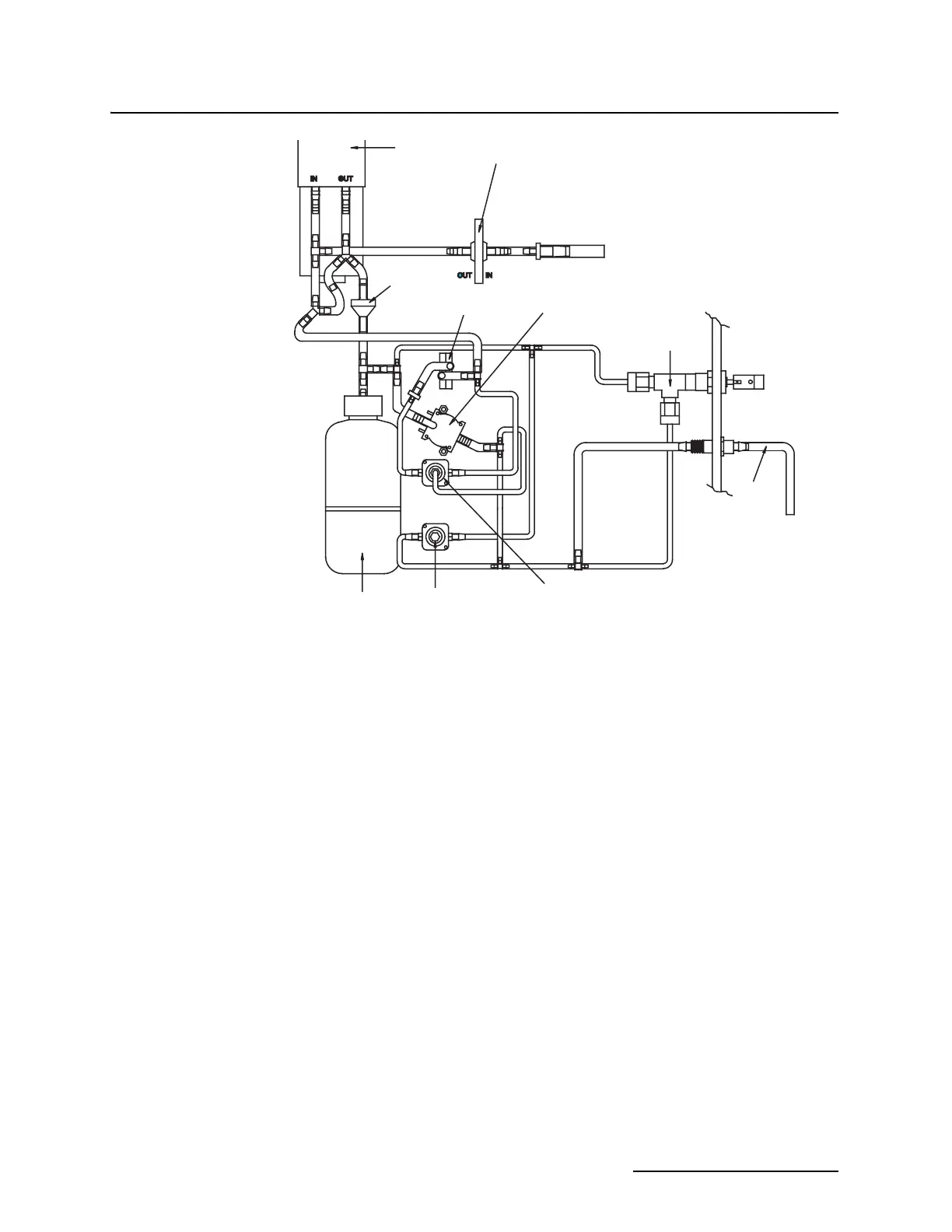
Figure 5-7 Schematic Diagram of the Bubbler System
While the purge valve pulses for short cycles to produce the
Super Bubble, it also opens to produce longer discharges of air at
intervals selected from the program, or you can operate it man-
ually through the use of the manual Purge switch on the keypad.
The purpose of the purge feature is to clear deposits from the
bubble line that build up over time and could eventually cause
clogging.
5.7.4 Pressure Transducer A temperature-compensated solid-state pressure transducer
measures the air pressure in the bubble line. The pressure is pro-
portional to the level. The pressure transducer connects to the
bubble line through the automatic drift compensation valve. The
reference side of this transducer vents to the outside of the case
through the external desiccator. The microprocessor converts the
output from this transducer into level and flow rate.
5.7.5 Automatic Drift
Compensation Valve
This valve, located directly across both ports of the pressure
transducer, turns on at power-up and from time to time after that
to tie the input and reference ports of the transducer together to
compensate for any drift that might occur. The software deter-
mines how often this valve turns on.
AIR PUMP
HYDROPHOBIC FILTER
CHECK VALVE
PRESSURE TRANSDUCER
BUBBLE RATE
ADJUST VALVE
BUBBLE
LINE
PURGE/SUPER
BUBBLE VALVE
AUTOMATIC DRIFT
COMPENSATION VALVE
AIR TANK
PRESSURE SENSOR