4230 Flow Meter
Section 4 Optional Equipment
4-27
CAUTION
The mounting ring may need anchoring. Under conditions of
high velocity (greater than five feet per second or 1.5 meters
per second), the mounting ring may not have sufficient out-
ward spring force to maintain a tight engagement with the pipe.
The ring may tend to lift off the bottom of the pipe in an oscilla-
tory fashion, or may even be carried downstream
This problem is more prevalent in the larger diameter pipes (10,
12, and 15 inch) and in pipes with a smooth inside surface (for
example, plastic). If any of these conditions are present, or if
movement of the mounting ring is detected or suspected, you
must anchor the ring in place. You can do this by shooting studs
through the ring into the pipe or by other appropriate means. In
some cases, it may be sufficient to simply increase the outward
spring force of the ring by bending it into a less round configu-
ration.
CAUTION
Use gloves and eye protection when assembling and installing
the rings in a pipe. Though deburred, the edges of the stain-
less steel can cut if improperly handled. Please read the fol-
lowing information on how best to install this device.
Observe general safety procedures when entering any man-
hole. See Appendix B Safety Considerations for more informa-
tion on general hazards and necessary precautions.
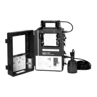
The Universal Mounting Ring is sold in sets assembled from
seven basic parts: base section, a scissors mechanism, four dif-
ferent sized extensions, and a hardware kit. This device mounts
Isco flow probes and parameter probes in closed cylindrical,
process or sewer pipes. The assembled rings can fit pipe diam-
eters from 18" to 72". Secure the unit in place by gently tight-
ening the supplied scissors mechanism with a
5
/8" socket wrench
or other suitable tool. Ring sections are .040" thick half-hard 301
stainless steel sheet. All other parts are also stainless steel,
except for the plastic cable ties in the hardware kit.
The scissors mechanism provides approximately 11
1
/2" of
adjustment, used to tighten the ring assembly. Each extension, 1,
2, 3, and 4, adds 7.5", 20", 30", or 40", respectively, to the circum-
ference of the ring. Used alone, the base section fits an 18"
diameter pipe. The 7.5" (the smallest) extension exists so that in
larger pipe sizes, where large variations in circumference can
occur, you can use either 0, 1, or 2 of these extensions to take up
or remove slack, to bring the scissors mechanism into a position
where it can be effectively tightened. The scissors mechanism
will work best if the respective assembly is installed to allow the
scissors to expand approximately in the middle of the
adjustment. Do not overtighten the mechanism: it is designed to
flex somewhat to provide a positive lock, once moderately
tightened.