Electrical installation
Page 104
8.11.3 EMC areas: first and second environment
Proper installation and wiring of all connecting cables provided, the item servo positioning controller C 1-Series fulfil the
requirements of product standard EN 61800-3. This standard no longer refers to "classes", but to so-called environments. The
first environment includes mains supply networks supplying residential buildings. The second environment includes mains
supply networks exclusively supplying industrial buildings.
The following applies to item servo positioning controller C 1-Series without external filter measures:
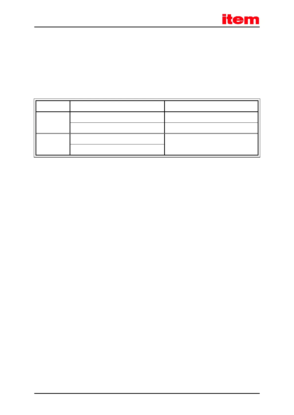
Table 42: EMC requirements: First and second environment
Compliance with EMC requirements
Interference
emission
First environment (domestic environment), C2 Motor cable length up to 25 m
Second environment (industrial environment), C3 Motor cable length up to 25 m
Interference
immunity
First environment (domestic environment), C2 Independent of motor cable length
Second environment (industrial environment), C3
8.11.4 EMC-compliant cabling
The following must be considered for an EMC-compliant setup of the drive system (see also
chapter
8
Electrical installation,
page 77
):
In order to keep the leakage currents and the losses in the motor connection cable as small as possible, the item servo
positioning controller C 1-Series should be located as close to the motor as possible (see also the following
chapter
8.11.5
Operation with long motor
cables
, page 105
)
Motor cable and angle encoder cable must be shielded
The shield of the motor cable is connected to the housing of the item servo positioning controller C 1-Series (shield connection
terminal). The cable shield also has to be connected to the associated servo positioning controller so that the leakage currents
can flow back into the controller causing the leakage
The mains-end PE connection is connected to the PE connection point of the supply connection [X9]
The inner PE conductor of the motor cable is connected to the PE connection point of the motor connection [X6]
The signal lines must be as far away from the power cables as possible. They should not be placed parallel. If intersections
cannot be avoided, they should be perpendicular (that is at a 90° angle), if possible
Unshielded signal and control lines should not be used. If their use is inevitable they should at least be twisted
Even shielded cables will inevitably have short unshielded ends (unless shielded connector housings are used). In general, the
following applies:
Connect the inner shields to the corresponding pins of the connectors; Maximum length 40 mm
Length of the unshielded cores 35 mm maximum
Connect the total shield on the controller side plane to the PE terminal; Maximum length 40 mm
Connect the total shield on the motor side plane to the connector housing or motor housing; Maximum length 40 mm

 Loading...