Electrical installation
Page 88
24
11
19
6
18
14
1
5
14
17
4
16
3
15
2
13
DOUT 3
DIN 9
DOUT 0
DIN 0
GND 24 V
+24 VDC
+VREF
AMON 0
AIN 1
AIN 0
Pin No.
X1
AMON 1
AIN 2
#AIN 0
AGND
AGND
DOUT x
GND 24 V
+24 VDC
+24 VDC
GN
D
GND 24 V
PEPE
100 mA
max !
100 mA
max !
Connector housing
+VREF
AIN 0
#AIN 0
AGND
AIN 1 / AIN 2
AGND
+15 V
AGND
AGND
AMON x
AGND
GN
D
AGND
DIN x
GND 24 V
GN
D
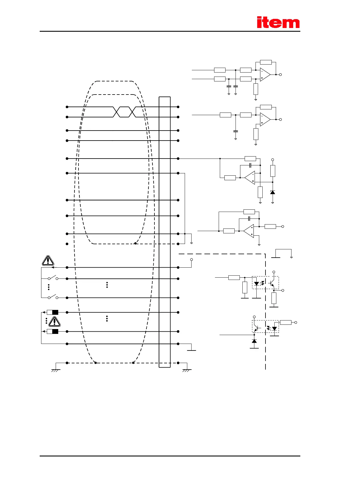
Control system item C 1-Series
Figure 20: Basic circuit diagram connector [X1]
The item servo positioning controller C 1-Series comprises one differential (AIN 0) and two single-ended analog inputs,
designed for input voltages within a range of ±10V. The inputs AIN 0 and #AIN 0 are lead to the control via twisted cables
(twisted pair design).
If the control comprises single-ended outputs, the output is connected to AIN 0 and #AIN 0 is put on the reference potential of
the control. If the control has differential outputs, they are to be connected 1:1 to the differential inputs of the item servo
positioning controller C 1-Series.
 Loading...
