Electrical installation
Page 81
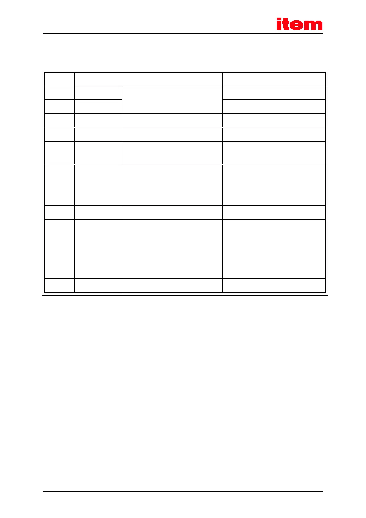
8.3.3 Pin assignment [X9]
Table 33: Pin assignment: [X9]
1 L 100 ... 230 VAC [± 10 %],
50 ... 60 Hz
Phase conductor
2 N Neutral conductor
3 ZK+ < 440 VDC Pos. DC bus voltage
4 ZK- GND_ZK Neg. DC bus voltage
5 BR-INT < 460 VDC Connection of internal brake resistor (bridge
to BR-CH when using the internal resistor)
6 BR-CH < 460 VDC
Brake chopper connection for internal brake
resistor against
BR-INT and external brake resistor against
ZK+
7 PE PE Connection ground conductor from mains
8 +24V 24 VDC
[± 20 %],
0,55 A
*)
0,65 A
*)
C 1-02
C 1-05 and
C 1-08
Supply for control module
9 GND24V GND (0 VDC) Reference potential supply
*)
Plus current consumption of a possibly connected holding brake and I/Os
8.3.4 Cable type and design [X9]
The mentioned cable denominations refer to cables by Lapp. They have proven effective and are successfully used in many
applications. However, similar cables from other manufacturers, for example Lütze or Helukabel, may also be used.
For the 230 VAC supply:
LAPP KABEL ÖLFLEX-CLASSIC 110; 3 x 1.5 mm²

 Loading...