Electrical installation
Page 94
8.7 Connection: CAN-Bus [X4]
8.7.1 Device side [X4]
D-SUB connector, 9-pole, female
8.7.2 Counterplug [X4]
D-SUB connector, 9-pole, male
Housing for 9-pole D-SUB connector with bolting screws 4/40 UNC
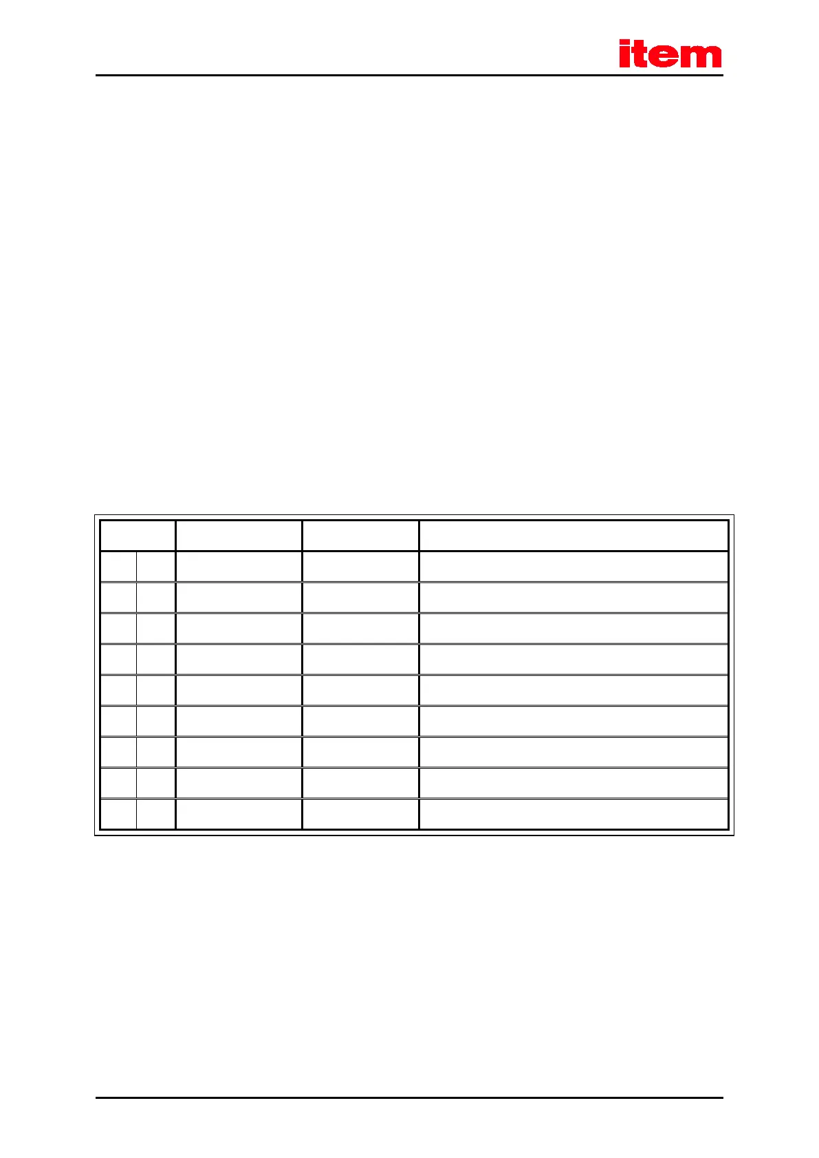
8.7.3 Pin assignment [X4]
Table 37: Pin assignment: CAN-Bus [X4]
1 Not occupied
6 GND 0 V CAN-GND, galvanically connected to GND in controller
2 CANL
*)
CAN-Low signal line
7 CANH
*)
CAN-High signal line
3 GND 0 V See Pin no. 6
8 Not occupied
4 Not occupied
9 Not occupied
5 Shield PE Connection for cable shield
*) External terminating resistor 120 Ω required on both ends of the bus. If the bus ends are not formed by
item C 1-Series servo positioning controllers with integrated terminating resistors, we recommend using metal film resistors with a 1 %
tolerance of type 0207, for example made by BCC, order no.: 232215621201.

 Loading...