Technology modules
Page 148
Table 46: Technical data: PROFIBUS-DP interface: Interfaces and communication
Controller PROFIBUS controller VPC3+, 12 Mbaud max.
Protocol PROFIBUS-DP,
32-byte telegrams with operating-mode-depending configuration
Interface Floating, D-SUB 9-pin, integrated bus terminating resistors
(can be activated by DIP switches)
Special functions Support of diagnosis data, RTS signal led out, fail-safe mode, sync/freeze
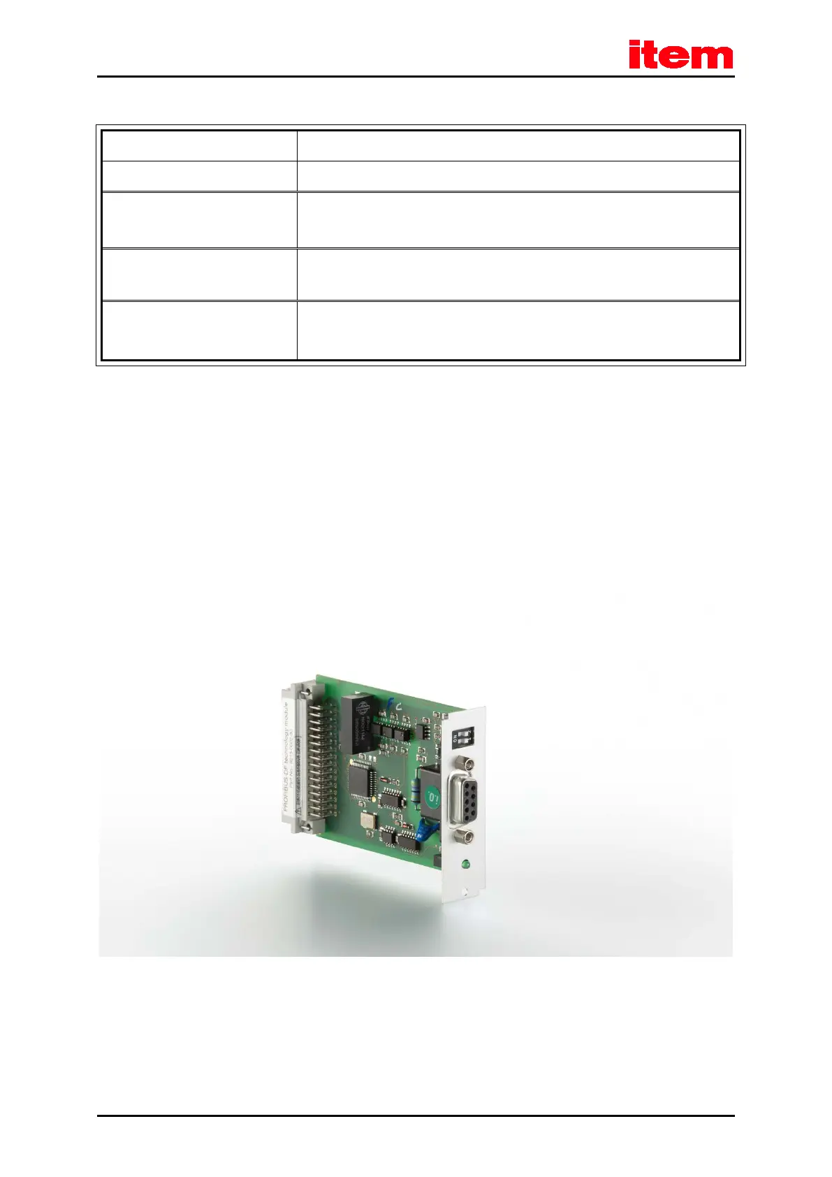
The following elements can be found on the front plate of the PROFIBUS-DP interface (see
Figure 27
):
a green LED to indicate readiness for operation
a 9-pin female DSUB connector
two DIP switches for activating the terminating resistors
Figure 27: PROFIBUS-DP interface: Front view

 Loading...