Technical data
Page 52
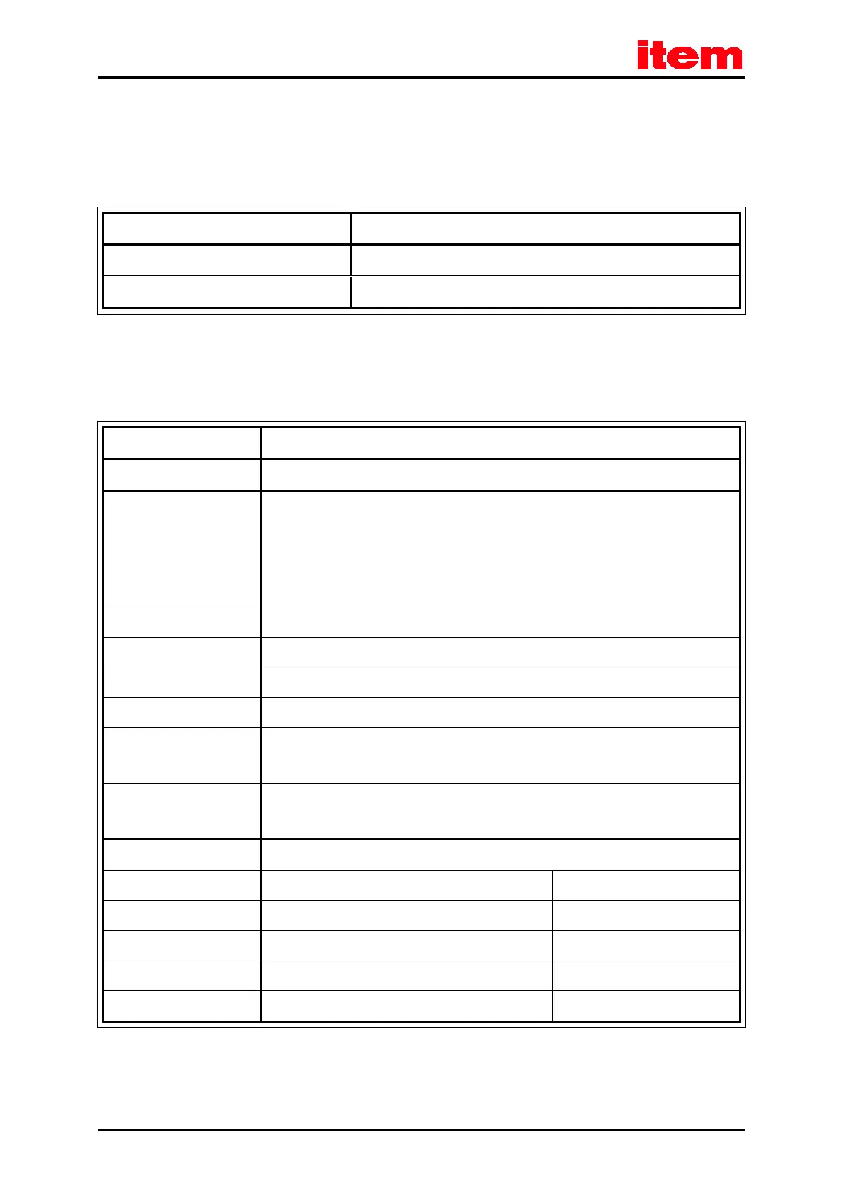
4.6.5 SD/MMC card
Table 25: Technical data: SD/MMC card
Card type SD, SDHC and MMC
File system FAT12, FAT16 and FAT32
4.6.6 I/O interface [X1]
Table 26: Technical data: Digital inputs and outputs [X1]
Signal level 24 V (8 V ... 30 V) active high, conforming with DIN EN 61131-2
Logic inputs general
DIN 0
DIN 1
DIN 2
DIN 3
Bit 0 \ (lsb least significant bit)
Bit 1, \ Target selection for positioning
Bit 2, / 16 targets selectable from target table
Bit 3 / (msb most significant bit)
DIN 4 Control input power stage (enable at High)
DIN 5 Controller enable at high signal, acknowledge error with falling edge
DIN 6 Limit switch input 0
DIN 7 Limit switch input 1
DIN 8 Control signal Start positioning or
Homing switch for homing or saving of positions
DIN 9 Control signal Start positioning or
Homing switch for homing or saving of positions
Logic outputs general Galvanically separated, 24 V (8 V ... 30 V) active high
DOUT 0 Operational state 24 V, max. 100 mA
DOUT 1 Freely configurable 24 V, max. 100 mA
DOUT 2 Freely configurable, optional use as input DIN 10 24 V, max. 100 mA
DOUT 3 Freely configurable, optional use as input DIN 11 24 V, max. 100 mA
DOUT 4 [X6] Holding brake 24 V, max. 1 A

 Loading...