37
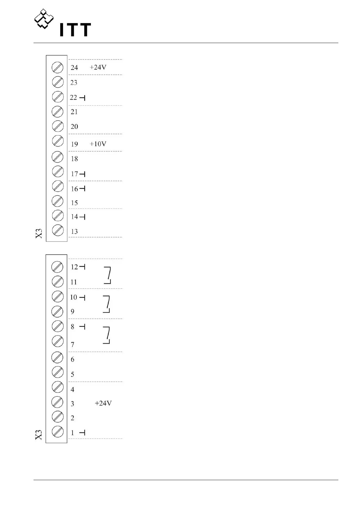
Additional Power supply ** max. 100 mA
Current signal input (Required Val. 2) 0-20mA / 4-20mA
[Ri=50Ω]
To determine the required value or the offset
Analogue Output 2 4-20mA [Ri=500Ω]
Analogue Output 1 0-10 VDC
Current signal input (Required Val. 1) 0-20mA / 4-20mA
[Ri=50Ω]
To determine the required value or the offset
Voltage signal input (Required Value 2) 0-10 VDC *DIG 4
To determine the required value or the offset
Voltage signal input (Required Value 1) 0-10 VDC
To determine the required value or the offset
Low water
e.g. incoming pressure switch or water level switch
Configurable Digital Input 1 DIG 1
e.g. for switching between 2 required values or sensors
External ON/OFF (release)
Actual-value-voltage input Sensor 1 0-10 VDC *DIG 2
Actual-value-voltage input Sensor 2 0-10 VDC *DIG 3
Actual-value-current input Sensor 2 0-20mA / 4-20mA [Ri=50Ω]
Sensor supply ** max. 100 mA
Actual-value-current input Sensor 1
0-20mA / 4-20mA [Ri=50Ω]
Ground
* Terminals X3/5 and 6 can be used as actual value voltage input and even as Digital Input without any
additional configuration. Also the voltage signal input on terminal X3/15 can be used as Digital Input.
** X3/3 and X3/24 – 24VDC and ∑ max. 100mA
 Loading...