JABLOTRON ALARMS a.s.
Pod Skalkou 4567/33 46601 Jablonec n. Nisou
Czech Republic www.jablotron.com
||
|
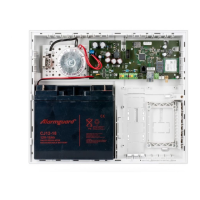
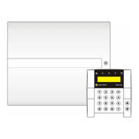
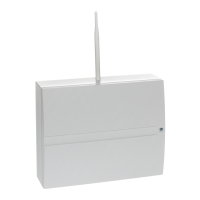
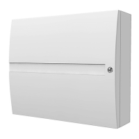
JA-101K(-LAN)(-LAN3G) and JA-106K(-3G)
Security System Control Panels
A control panel is a fundamental part of the JABLOTRON 100 series alarm system and is designed to protect
small, medium or large premises and complies with security grade 2 requirements. The control panel has BUS
and/or wireless device (when the system is equipped with a radio module) compatibility. It is recommended that
only JABLOTRON 100 devices are used with the system. Proper functionality cannot be guaranteed when using
third party devices.
Caution: The JABLOTRON 100 security system can only be installed by a trained technician with a valid
certificate issued by an authorized distributor.
The manual is intended for trained technicians and is valid for control panel firmware LJ60418 and
MD60418 and the configuration software F-Link 1.4.0 or higher.
Contents
1 Basic description and definitions ................................................................................................................ 4
1.1 Basic system configuration requirements ........................................................................................... 7
1.2 Access codes and their default settings ............................................................................................. 9
1.2.1 Change of access codes ............................................................................................................ 9
1.2.2 Security access codes and RFID devices ................................................................................. 10
1.2.3 Regular system check (maintenance) ....................................................................................... 10
2 System size............................................................................................................................................. 12
2.1 External size .................................................................................................................................... 12
2.2 Internal size (system range) ............................................................................................................. 12
2.2.1 Configuration and splitting ........................................................................................................ 13
3 Types of control panels, utility parameters ............................................................................................... 14
3.1 Description of JA-101K(-LAN)(-LAN3G) / JA-101KR(-LAN)(-LAN3G) ............................................... 15
3.2 Description of JA-106K(-3G) / JA-106KR(-3G) ................................................................................. 16
3.3 Indication LEDs on the control panel board ...................................................................................... 18
3.4 Additional Connectors on the control panel PCB .............................................................................. 18
3.5 Connection terminals on the control panel PCB................................................................................ 18
4 Before system installation ........................................................................................................................ 19
5 Installation of BUS devices ...................................................................................................................... 20
5.1 JA-100 BUS ..................................................................................................................................... 20
5.2 BUS cables...................................................................................................................................... 20
5.3 BUS layout ...................................................................................................................................... 21
5.4 BUS branching and splitting ............................................................................................................. 21
5.5 BUS length and numbers of connected devices ............................................................................... 21
5.6 Calculation of line losses ................................................................................................................. 22
5.7 Example of a voltage loss calculation: .............................................................................................. 22
5.8 Example of calculation of BUS consumption to back-up the system ................................................. 23
5.9 Power supply requirements .............................................................................................................. 24
5.10 Backup requirements ....................................................................................................................... 24
5.11 BUS isolation ................................................................................................................................... 24
5.12 Use of existing cabling in refurbishment projects. ............................................................................. 25
6 Use of wireless devices ........................................................................................................................... 25
6.1 Installation of a JA-11xR radio module ............................................................................................. 25
6.2 Installation of wireless devices – enrollment mode .......................................................................
.... 25
7 Switching the system ON......................................................................................................................... 26
8 System configuration ............................................................................................................................... 26
8.1 The system profiles .......................................................................................................................... 26
8.2 Control panel operation modes ........................................................................................................ 30
8.3 Authorisation of users ...................................................................................................................... 31
8.4 System optional parameters ............................................................................................................ 31
8.4.1 Enrolling and erasing devices ................................................................................................... 33
8.4.2 List of applicable reactions ....................................................................................................... 34
8.4.3 Limitation of false alarms .......................................................................................................... 35
8.5 Types of alarms ............................................................................................................................... 37