8
Operation Manual
valve that maintains the proper water level. A
low level switch mounted on the back of the
tank shuts off the engine in the event that the
tank runs low on water (control panel displays
“Emergency Stop”). An overow port (elbow t-
ting) is located on the side of the tank slightly
above the inlet elbow. This tting acts as a
vent and must always remain open to atmo-
sphere. Do not plug or plumb this tting.
This tank is not intended to sustain blasting
operations for more than a few minutes.
Manifold
The manifold houses many of the components
that make up the uid end of the pump in-
cluding the uni-valves. The three uni-valves
each consist of a suction and discharge valve
combined into one assembly. The valves con-
vert low pressure water to high pressure water.
Manifold Drain Valve
The manifold drain valve allows the manifold
to be ushed of contaminants prior to pump
usage. It is also used to purge air during op-
eration start up.
Water Lubrication System
The water lubrication system provides water
to the packing in the pump. The water lubri-
cates and cools for optimum operation of the
pump. The system includes a manifold and
three water lines. Needle valves are present
on manifolds that are pressure fed (all 40K
units). The needle valves control the amount of
ow to each stufng box and must be prop-
erly adjusted during operation. Manifolds that
are not pressure fed have a xed ow. Refer to
“Charge Pump (40K Units)” on page 12 for
more information on pressure fed manifolds.
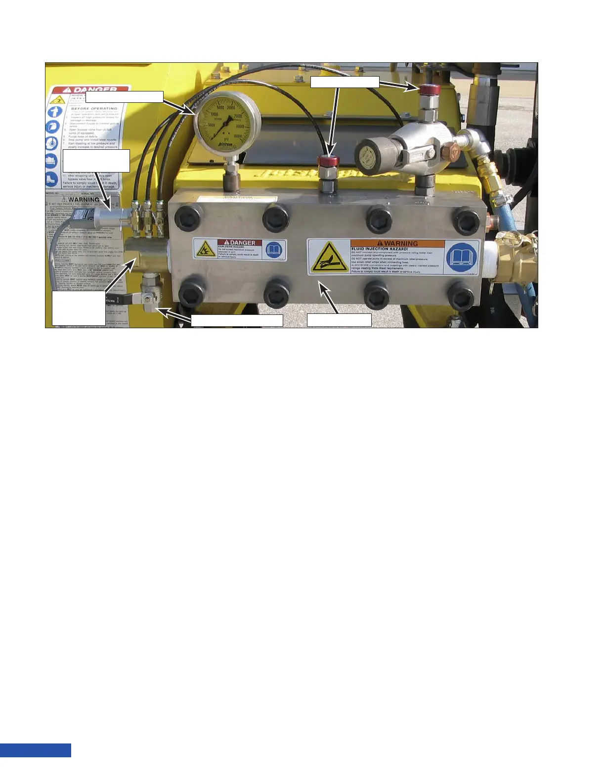
Pressure Gauge
The liquid lled pressure gauge allows the
operator controlling the pump to monitor the
pressure of the system.
Hydro-Throttle Switch (Optional)
The hydro-throttle switch senses the pressure
within the pump and allows the engine to idle
when the operator is not blasting.
Refer to “Using the Hydro-Throttle (Dump Sys-
tem Only)” on page 29.
Pressure Gauge
Hydro-Throttle
Switch
Water
Lubrication
System
Manifold Drain Valve
Manifold
Rupture Discs
Figure 9: Pump Components