84
Operation Manual
Installation
1. Place the crosshead/connecting rod
assemblies into position inside of the
crankcase.
2. Install the crankshaft as outlined in “In-
stallation” on page 87.
UNx Pump
Removal
1. Drain the water tank.
2. Remove the bypass hose and supply hose
(Figure 172). If the supply hose is con-
nected to the secondary lter, disconnect
it from the lter.
3. Remove the two screws that secure the
hydro-throttle switch housing to the car-
tridge and disconnect the switch.
4. If equipped, the secondary lter switch
must be disconnected. Remove the two
screws that secure the switch cover (Figure
173) and disconnect the wiring. Unscrew
the conduit tting from the switch housing
and lay the conduit and wiring aside.
5. Remove the belts as outlined in “Replac-
ing the Belts” on page 73.
6. Use a marker to mark the location of the
pump footings for easier installation.
7. Remove the four pump mounting cap-
screws and nuts.
8. Attach a hoist and lifting apparatus to the
pump as shown in (Figure 174). The weight
of the pump is approximately:
• 3000 Series: 1200 lb. (544 kg)
• 3600/4200 Series: 2200 lb. (998 kg)
9. Lift the pump from the unit and place in a
suitable location for servicing.
10. If shims were under the pump, keep the
shims together and note their proper
location.
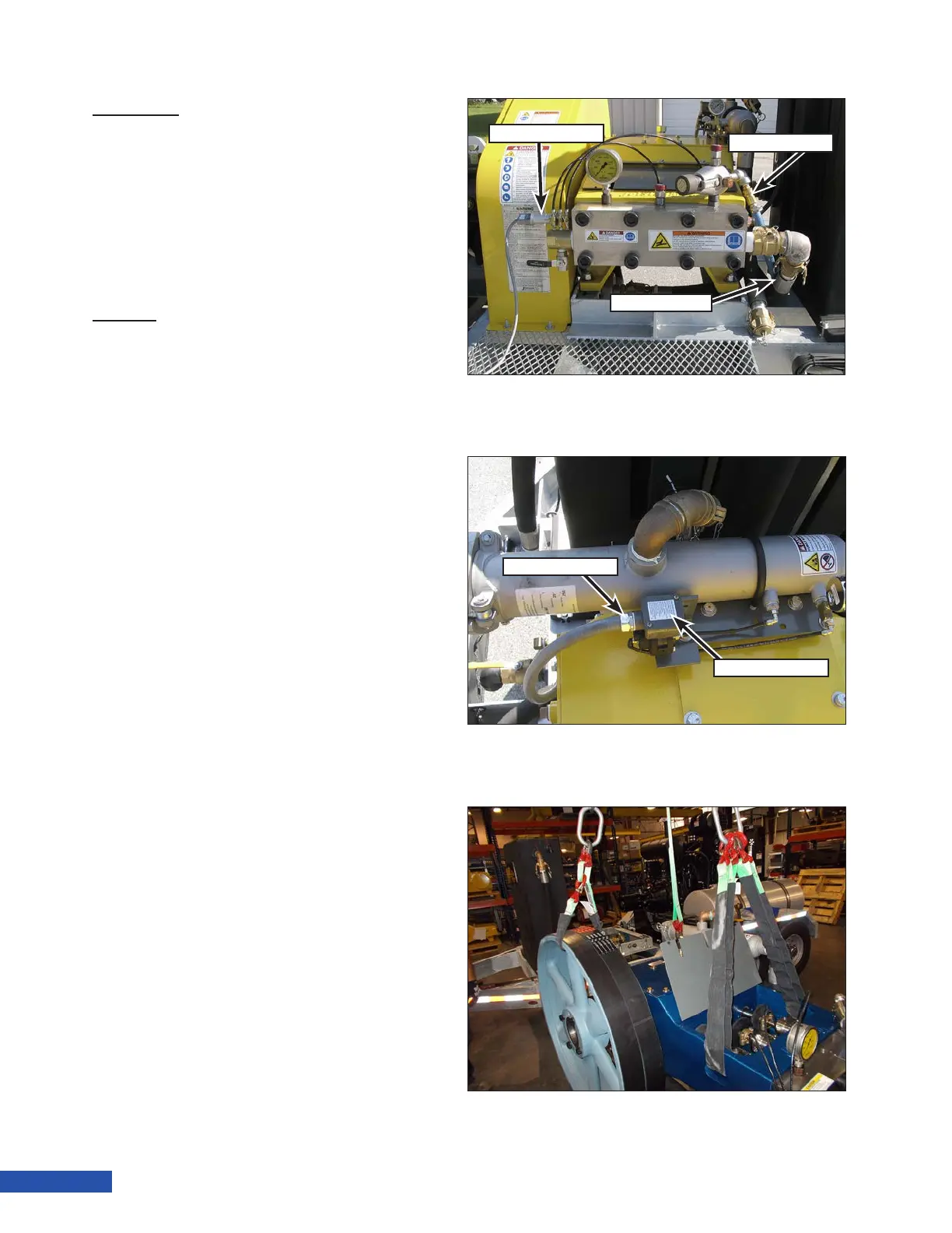
Figure 174: Lifting the Pump.
Figure 172: Pump Removal Preparation.
Throttle Switch
Bypass Hose
Supply Hose
Figure 173: 40K Switch Wiring.
Conduit Fitting
Switch Cover