19
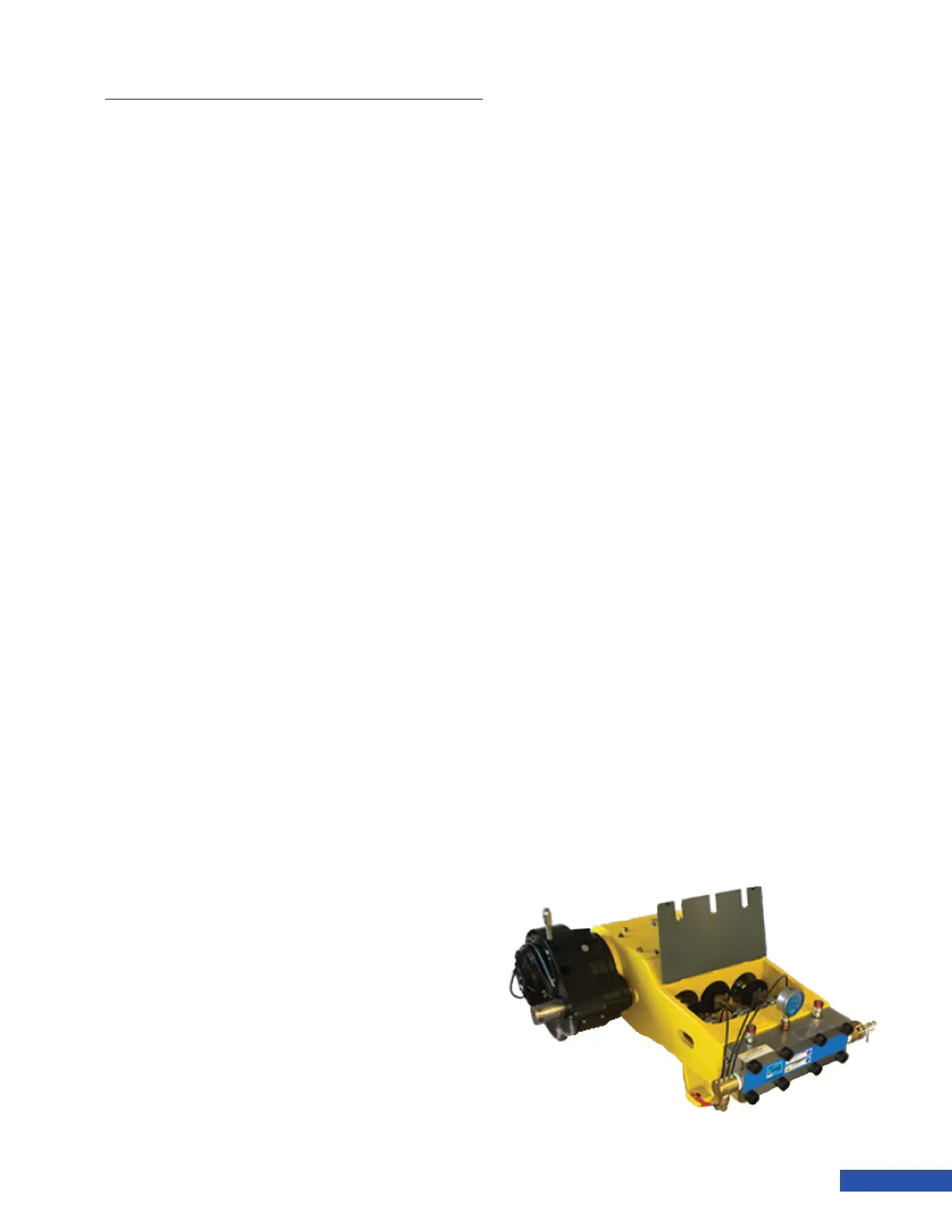
X-Series Waterblast Unit
Jetstream 3000/3600/4200
Bareshaft Pump Installation
Guidelines
Models
The Jetstream UNx bareshaft pump is avail-
able in three horsepower ranges and three
pressure ranges – 15,000 psi, 20,000 psi, or
40,000 psi and can be supplied with an op-
tional geardrive. The geardrive is available
in four different gear ratios to support die-
sel engine or electric motor input speeds.
Both styles can be supplied left hand drive
or right hand drive (as viewed from FE) and
the geardrive model’s input shaft can also
be clocked to ve different locations. The
geardrive unit requires inline drive with
exible coupling***. The standard unit can
be inline or belt driven via pulleys exerting a
side load on the crank- shaft. All Jetstream
powerends have a preferred rotation direction
(top of crankshaft towards the uid end) that
is marked on the casting. However reverse
rotation operation is allowed with the addition
of optional reverse rotation oil scrapers. The
geardrive requires a clockwise input rotation
direction.
3000 series 150 hp max 600 rpm max
3600 series 175 hp max 550 rpm max
4200 series 325 hp max 518 rpm max
Water Supply
The 15K and 20K versions can be gravity fed
(water level 3’ minimum above the manifold
suction inlet). The 40K version requires 40 psi
minimum supply pressure at full pump speed
to operate. All uid ends have a maximum
inlet supply pressure of 75 psi.****
The supply water should be clean and cold. The
maximum allowed inlet water temperature
is 125°F. Ideally the water should be ltered
to 25 micron (3 micron for 40K) and 40-80°F
for maximum packing life. Severly reduced
packing life will be encountered with warmer
water. The inlet supply hose should be 3” ID if
gravity fed and 2” ID if pressure fed. Jetstream
recommends oileld suction hose as it has
proven to be durable with a relatively small
bend radius. The hose should be as short and
straight as possible with no additional ttings
(elbows) - especially important with gravity
fed setup. If bends are required it is best to
bend the hose without the use of elbows.
The plunger packing is lubricated with the
supply water and is not adjustable on nor-
mal gravity fed 15K/20K systems. On 40K and
pressure fed systems, the lube harness needs
to be equipped with needle valves to allow
adjustment of the lube water ow. The cooling
water should exit the rear of the gland nuts
with a steady stream (more than a drip) but
not enough to be splashed onto the pony rod
during operation.
Pulsation
Positive displacement pumps create pulsa-
tion in the high pressure discharge line. For
this reason, it is extremely important to utilize
exible hoses (ie rubber, thermoplastic) in lieu
of rigid piping to minimize water hammer and
vibration. If rigid piping is necessary, it should
not be installed at the pump discharge. A 25’
or 50’ section of hose should be installed at
the pump discharge. This length can be coiled
and hung for space savings. A high pressure
pulsation damper may be benecial in some
cases. Short on/off cycles at high pressure will
create the largest spikes of pressure and re-
quire care to damp- en. Flow controls or other
means to slow the abrupt change of pressure
will smooth these pulsations.