27
X-Series Waterblast Unit
11. Reduce the discharge ow by fully open-
ing the bypass valve.
12. With the engine at idle speed, disengage
the clutch.
13. The nozzles can now be installed on the
discharge device(s).
14. Before waterblasting, adjust the lubrica-
tion line needle valves, if equipped. Refer
to “Checknig the Water Lubrication Sys-
tem” on page “Checking the Water Lubri-
cation System” on page 27 .
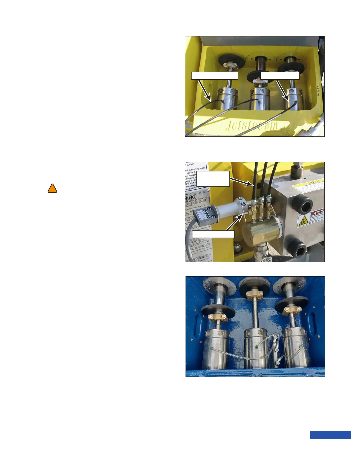
Checking the Water Lubrication
System
1. Lift the rod box cover to view the water
lubrication system.
2. Look into the rod box and verify that lu-
brication water is owing from the back
of the gland nut at the plunger/gland nut
intersection. The ow should be a small
stream but should not splash onto the
pony rods. (Figure 35).
3. Next, check the stufng box temperature
by very carefully placing your nger tips
on the top of the stufng box. The temper-
ature should be cool to warm but still cool
enough that you can keep your ngers on
it for 10 seconds.
If there is no water ow, or the tempera-
ture is too hot, or if steam is visible, the
needle valves need to be adjusted.
4. Adjust the needle valves (Figure 36)
(needle valves are only included on pres-
sure fed setups. Gravity fed units will not
utilize needle valves) to increase the
water ow. Excessive splashing may
occur, which could cause water to be
drawn into the power end, contaminating
the oil. Adjust the needle valves to pre-
vent excessive lubrication water ow.
Re-check the lubrication water ow
periodically during operation.
WARNING
!!
There are moving parts inside the rod box that can
cause serious injury. Use extreme caution. Keep all
tools out of the rod box while the pump is running.
Lubrication Line
Needle
Valve
Lubrication Line Stuffing Box
Figure 35: Checking Lubrication.
Lubrication
Line
Needle Valve
Figure 36: Needle Valve Adjustment (40K).
Figure 37: 5200 Series Water Lubrication System.