88
Operation Manual
7. Place the three crosshead/connecting rod
assemblies into place (Figure 184). Allow
clearance for the crankshaft by pushing
them towards the uid end.
8. Install two threaded rods (1 in.-8NC x 8 in.)
into the ends of the crankshaft to aid in
installation.
9. Using two people, lift the crankshaft into
the power frame. The weight of the crank-
shaft is approximately:
• 3000 Series: 125 lb. (57 kg)
• 3600/4200 Series: 325 lb. (147 kg)
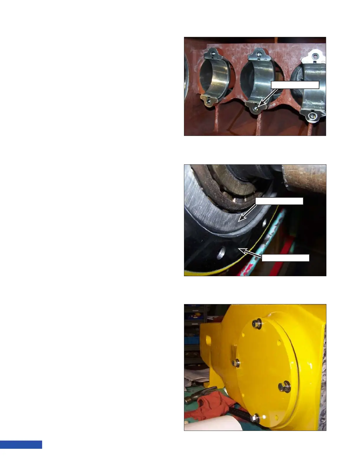
10. Using a wood block and a hammer, hit
either end of the crankshaft to seat it in
the bearing bore. Ensure the outer bear-
ing race (Figure 185) is inside the power
frame case.
11. Tap in the bearing race on the opposite
end of the crankshaft if not already in-
stalled.
12. Install a new oil seal and O-ring onto the
inboard side plate. Install the outboard
and inboard side plates with the original
shim packs. Ensure the thickness of each
shim pack is equal on both ends. Install
four equally spaced side plate capscrews
and tighten to 50 ft.lb (68 N·m) (Figure
186).
Figure 184: Connecting Rod Installation.
Connecting Rod
Bearing Race
Power Frame
Figure 185: Crankshaft Seating.
Figure 186: Side Plate Installation.