86
Operation Manual
Crankshaft
Removal
1. Remove the pump from the unit. Refer to
“UNx Pump” on page 84.
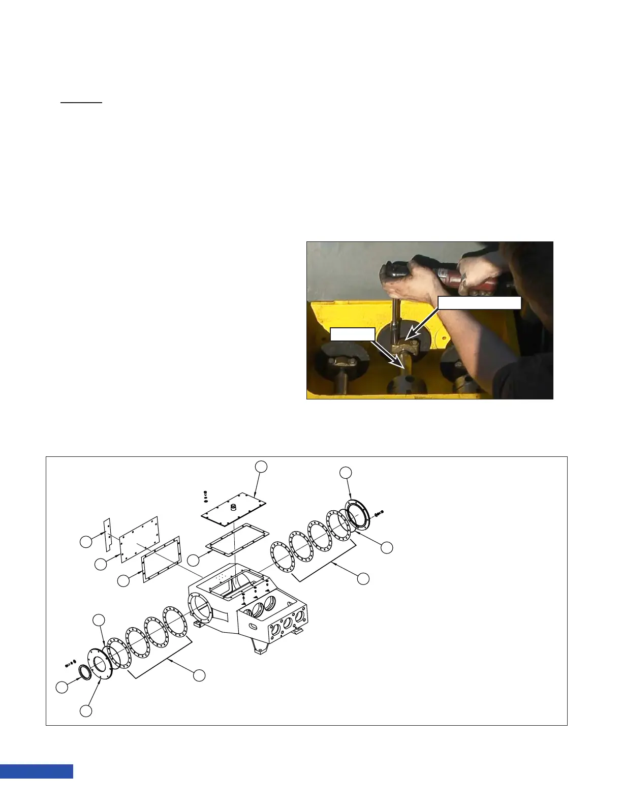
2. Open the rod box cover and remove the
two capscrews that secure the plunger
coupling (Figure 179) to the plunger and
remove the coupling.
Note: The coupling halves are a
machined pair. Keep the two
halves together.
3. Remove the connecting rod end caps as
outlined in “Rod Journal Bearings” on
page 78.
4. Remove the 12 capscrews and washers
that secure the top cover (Figure 180) to
the power frame. Remove the cover and
the gasket.
5. Remove the 12 capscrews and washers
that secure the rear cover (Figure 180) and
belt guard to the power frame. Remove
the cover, guard and gasket.
6. Pull the three connecting rod/crosshead
assemblies towards the uid end as far
as possible.
7. Remove the eight capscrews and washers
that secure the inboard side plate (Figure
180) to the power frame.
8. Remove the side plate and shims. Keep
the shims together.
9. Remove the eight capscrews and wash-
ers that secure the outboard side plate
(Figure 180) to the power frame.
Plunger Coupling
Plunger
Figure 179: Plunger Coupling Removal.
1. Top Cover
2. Gasket
3. Outboard Side Plate
4. O-ring
5. Shim Pack
6. Shim Pack
7. Inboard Side Plate
8. Oil seal
9. O-Ring
10. Gasket
11. Rear Cover
12. Belt Guard
Figure 180: Power End Covers.