16
Operation Manual
Trailer Breakaway System
The trailer is equipped with a breakaway system
in the event that the trailer should come un-
hitched from the tow vehicle. If this occurs, the
breakaway system will apply the trailer brakes to
bring the trailer to a stop.
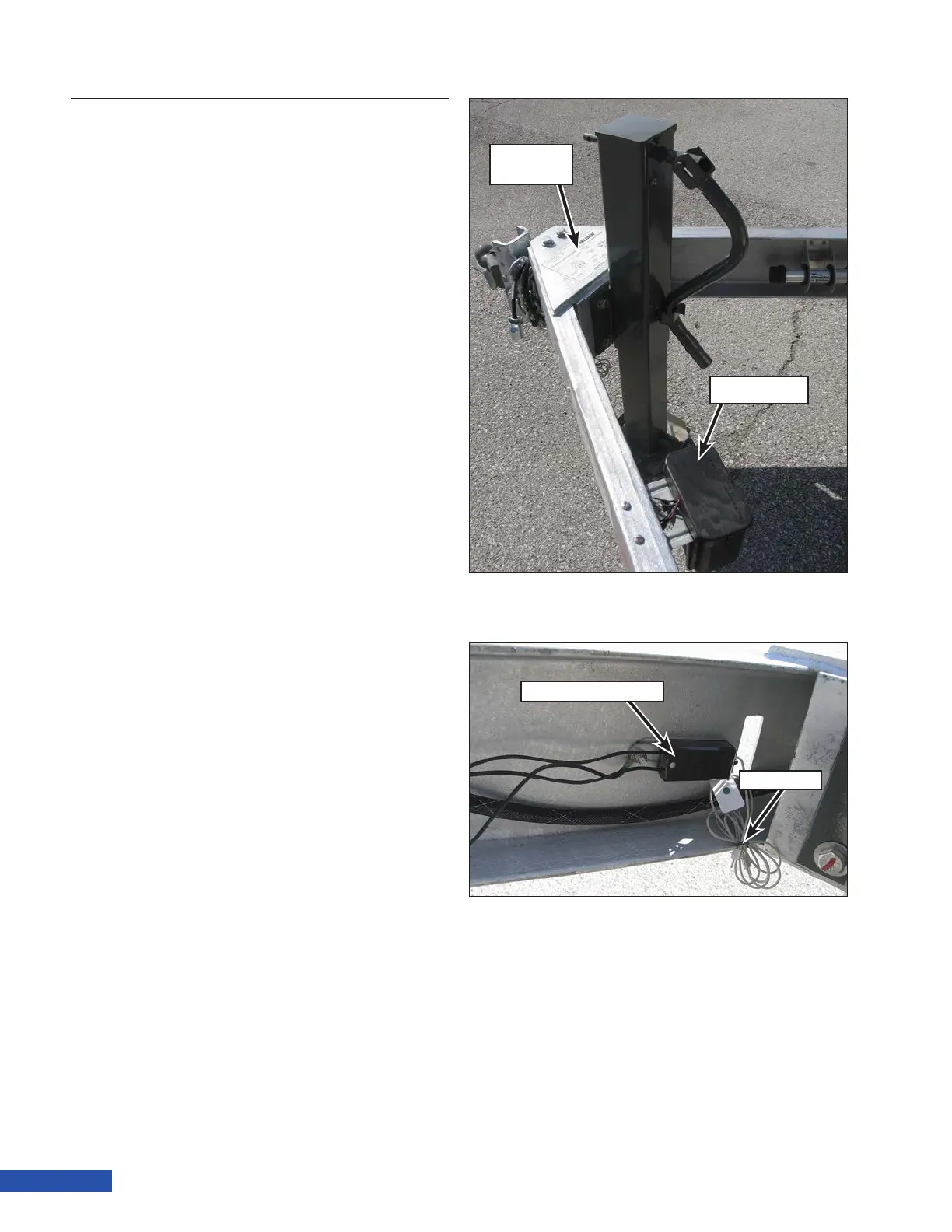
The breakaway system includes a battery (Fig-
ure 25) and a breakaway switch (Figure 26).
Both components are located near the nose of
the trailer on the left hand inside rail, adjacent
to the jack stand.
In the event of a separation, the lanyard (Fig-
ure 26) would be pulled from the breakaway
switch which closes a set of contacts. Voltage
from the breakaway system battery is sent
through the closed contacts in the switch to
the brake magnets in the drum brakes. The
magnet actuates the brakes to stop the trailer.
The battery is connected to the tow vehicle
charging system, if properly wired, to provide
charging when being towed. Check the battery
for proper voltage before towing.
Refer to the connector wiring decal (Figure
25) located on top of the tongue in front of the
jack stand.
Activating the System
1. When attaching the trailer to the tow ve-
hicle, attach the loose end of the lanyard
to the tow vehicle hitch.
2. Ensure the trailer electrical connector is
properly connected.
Connector
Decal
Battery
Figure 25: Battery and Connector Decal.
Breakaway switch
Lanyard
Figure 26: Breakaway Switch.