11
X-Series Waterblast Unit
bottom of the tank is connected to a hose that
is routed to the side of the unit. A drain valve
(Figure 12) is connected to the end of the hose
to easily drain the water tank when nished
waterblasting. Always drain the tank before
towing the trailer. Refer to “Water Tank and
Filtration” on page 39 for more information
on the water tank.
Secondary Filter (40K Units)
A secondary lter (Figure 13) is mounted on
top of the pump for use when operating at
“40K”. The lter is not connected during 15K or
20K operation.
A pressure gauge is mounted on the lter to
monitor pressure in the lter.
A differential pressure switch is mounted
in the lter circuit to monitor proper ow
through the lter. If the lter becomes plugged
and ow is insufcient, the switch will cause
the engine to shut off. “Emergency Stop” will
be displayed on the control panel.
A drain valve is located on the lter cover that
allows the operator to purge air from the lter
at startup.
Fuel Tank
The 130 gal (573 L) fuel tank (Figure 14) is
located next to the engine. A mechanical oat
style fuel gauge is located on the top to inform
the operator of the amount of fuel in the tank.
Note:
An option for an electronic fuel
sender that relays fuel level to the
control panel is also available.
Contact Jetstream for more infor-
mation.
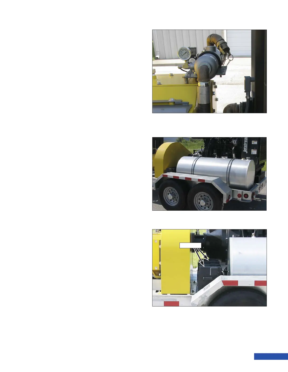
Batteries
Two 12 volt lead acid batteries wired in paral-
lel (12V), unless otherwise stated, are located
in between the belt drive and the fuel tank
(Figure 15). The batteries and connections are
contained in two rain proof containers.
Figure 13: Secondary Filter
Figure 14: Fuel Tank
Figure 15: Batteries
Batteries