80
Operation Manual
6. Measure the attened plasti-gauge using
the gauge wrapper (Figure 161).
7. If the thickness of the plasti-gauge
exceeds 0.012 in. (0.31 mm), replace the
bearings. If the bearings do not exceed
the criteria, the bearings can be reused.
Note: New part clearances are as fol-
lows:
• Series 3000: 0.001 in. (0.025 mm) - 0.005
in. (0.13 mm)
• Series 3600/4200: 0.002 in. (.05 mm) -
0.005 in. (0.13 mm)
Installation
1. Apply clean new oil to the new connecting
rod journal bearing (inner diameter only)
(Figure 162).
2. Slide the bearing (Figure 163) into the
connecting rod from below the crankshaft
journal.
3. Apply oil to the inner surface of the cap
end bearing.
4. Properly orient the grooves and install the
bearing in the rod cap.
5. Place the two capscrews into the rod cap.
ATTENTION
The journal bearings have tabs that match the
inner diameter of the connecting rods. Ensure the
bearings are properly oriented in the tabs when
installing (Figure 164).
Figure 161: Plasti-Gauge Measurement.
Figure 162: Lubricating the Bearing.
Figure 163: Rod Bearing installation.
Journal Bearing
Crankshaft
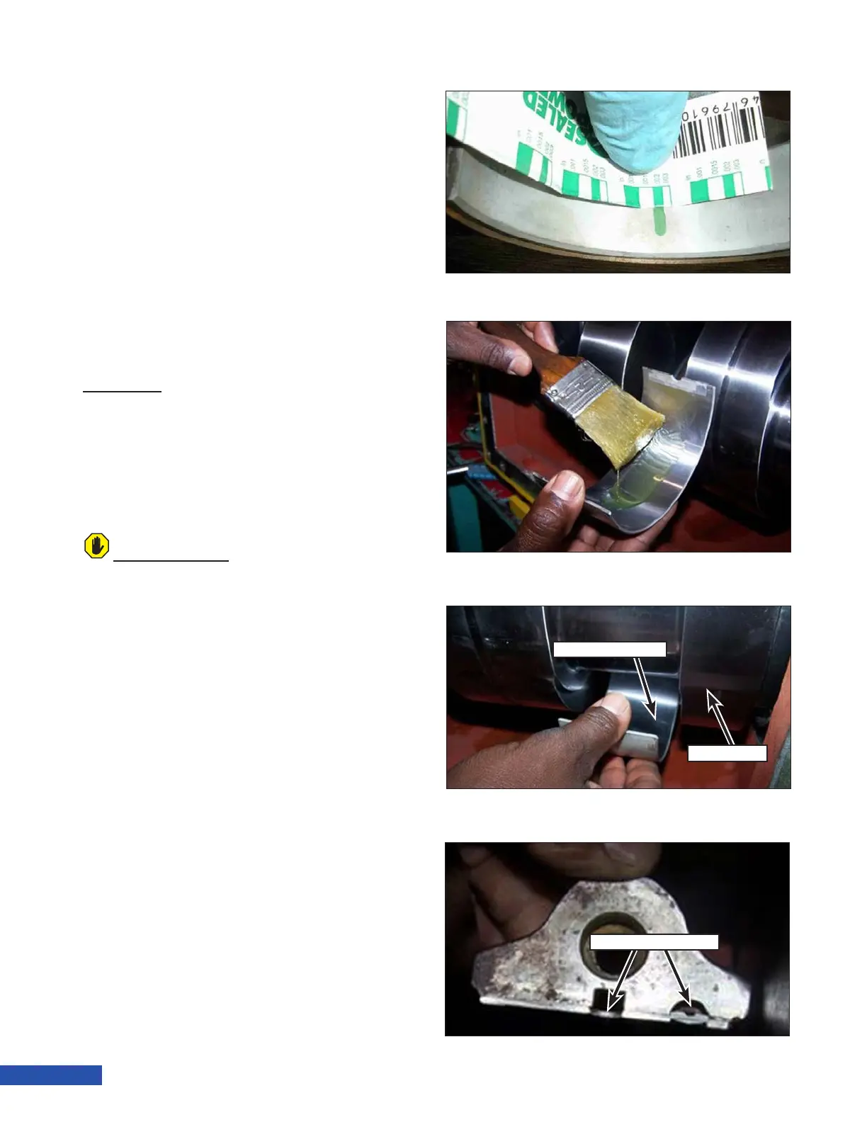
Figure 164: Bearing Grooves.
Bearing Grooves